67
6
F
2
S
0
8
5
0
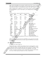
BRRS
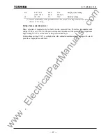
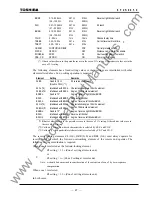
0.10 - 20.00
Ω
0.01
Ω
5.10
Ω
Reverse right blinder reach
(0.5 - 100.0
Ω
0.1
Ω
25.5
Ω
)
Z4G
0.01 - 100.00
Ω
0.01
Ω
8.00
Ω
Z4 reach
(0.1 – 500.0
Ω
0.1
Ω
40.0
Ω
)
BRRG
0.10 - 20.00
Ω
0.01
Ω
5.10
Ω
Reverse right blinder reach
(0.5 - 100.0
Ω
0.1
Ω
25.5
Ω
)
TCHD
0 - 50 ms
1 ms
12 ms
Channel delay time
TREBK
0.00 - 10.00s
0.01s
0.10s
Current reversal block time
TSBCT
0.00 – 1.00s
0.01s
0.10s
CRSCM
PUP/POP/UOP/BOP
POP
Carrier protection mode
DISCR OFF/ON
OFF
Distance carrier protection enable
ZONESEL
Z2/Z3
Z2
Overreaching element selection
PSB - CR
OFF/ON
ON
Power swing blocking
(*) Ohmic values shown in the parentheses are in the case of 1 A rating. Other ohmic values are in the
case of 5 A rating.
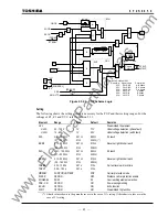
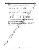
The following elements have fixed setting values or their settings are interlinked with other
elements listed above. So no setting operation is required.
Element Setting
Remarks
Z4BS
Fixed to 1.5
Ω
Z4 reverse offset reach
(Fixed to 7.5
Ω
) (*1)
Z4S
θ
(*2)
Interlinked with Z3S
θ
Characteristic angle of Z4 mho element
Z4BS
θ
(*3)
Interlinked with ZBS
θ
Angle of Z4 directional element
BRRS
θ
Fixed to 75°
Angle of reverse right blinder BRRS
BRLS
Interlinked with BRRS Reverse left blinder
BRLS
θ
Interlinked with BFLS
θ
Angle of reverse left blinder BRLS
Z4G
θ
(*2)
Interlinked with Z3G
θ
Characteristic angle of Z4 mho element
Z4BG
θ
(*3)
Interlinked with ZBG
θ
Angle of Z4 directional element
BRRG
θ
Fixed to 75°
Angle of reverse right blinder BRRG
BRLG
Interlinked with BRRG Reverse left blinder
BRLG
θ
Interlinked with BFLG
θ
Angle of reverse left blinder BRLG
(*1)Ohmic values shown in the parentheses are in the case of 1 A rating. Other ohmic values are in
the case of 5 A rating.
(*2) Valid only when mho-based characteristic is selected by ZS-C and ZG-C.
(*3) Valid only when quadrilateral characteristic is selected by ZS-C and ZG-C.
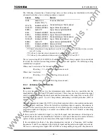
The reverse looking elements Z4 (G,S), BRR (G,S) and BRL (G,S) must always operate for
reverse faults for which the forward overreaching element of the remote end operates. The
following setting coordination is required.
When zone 2 is selected as the forward-looking element,
Z4 setting = 1.2
×
(Zone 3 setting at remote end)
or
Z4 setting =
α
×
(Zone 2 setting at remote end)
Note:
α
should be determined in consideration of the extension of zone 2 by zero-sequence
compensation.
When zone 3 is selected,
Z4 setting = 1.2
×
(Zone 3 setting at remote end)
In both cases,
www
. ElectricalPartManuals
. com
Summary of Contents for GRL100-701B
Page 329: ... 328 6 F 2 S 0 8 5 0 w w w E l e c t r i c a l P a r t M a n u a l s c o m ...
Page 339: ... 338 6 F 2 S 0 8 5 0 w w w E l e c t r i c a l P a r t M a n u a l s c o m ...
Page 351: ... 350 6 F 2 S 0 8 5 0 w w w E l e c t r i c a l P a r t M a n u a l s c o m ...
Page 381: ... 380 6 F 2 S 0 8 5 0 w w w E l e c t r i c a l P a r t M a n u a l s c o m ...
Page 413: ... 412 6 F 2 S 0 8 5 0 w w w E l e c t r i c a l P a r t M a n u a l s c o m ...
Page 417: ... 416 6 F 2 S 0 8 5 0 w w w E l e c t r i c a l P a r t M a n u a l s c o m ...
Page 453: ... 452 6 F 2 S 0 8 5 0 w w w E l e c t r i c a l P a r t M a n u a l s c o m ...
Page 457: ... 456 6 F 2 S 0 8 5 0 w w w E l e c t r i c a l P a r t M a n u a l s c o m ...
Page 473: ...w w w E l e c t r i c a l P a r t M a n u a l s c o m ...

