119
6
F
2
S
0
7
8
9
6.5.1.2 2F element
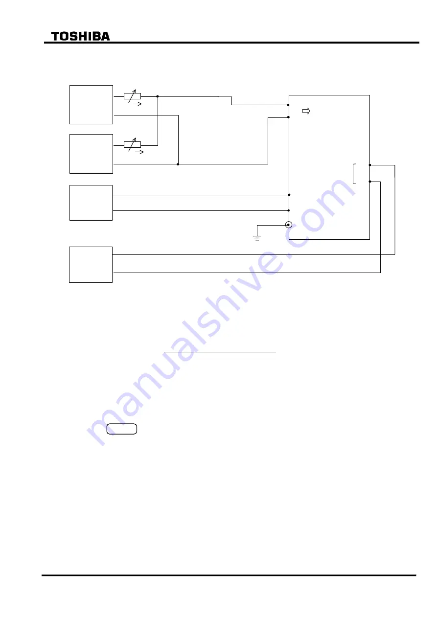
The testing circuit is shown in Figure 6.5.5.
Current
source
TB 1
DC
voltmeter
TB 4
-1
-2
- A16
- A17
GRT100
DC
power
supply
Monitoring
jack
A
0V
Current
source
50 or 60Hz
100 or 120Hz
I a
I 1
I 2
Figure 6.5.5 Testing 2F Element (Model 100s, 200s)
The output signal number of the 2F element is as follows:
Element
Signal number
2F
122
Set the second harmonic restraint setting k2f to 15%(= default setting).
Press 4 (= Logic circuit) on the "Test" sub-menu screen to display the "Logic circuit"
screen.
Enter a signal number to observe the 2F output at monitoring jack A and press the
ENTER
key.
Set the fundamental frequency current I
1
to 3 times of ik setting. Change the magnitude of
the second harmonic current I
2
and measure the value at which the element operates.
Calculate the percentage of the second harmonic by I
2
/I
1
when the element operates.
Check that the percentage is within 7% of the k2f setting.
Summary of Contents for GRT100 Series
Page 142: ... 141 6 F 2 S 0 7 8 9 Appendix A Block Diagram ...
Page 144: ... 143 6 F 2 S 0 7 8 9 Appendix B Signal List ...
Page 159: ... 158 6 F 2 S 0 7 8 9 ...
Page 160: ... 159 6 F 2 S 0 7 8 9 Appendix C Variable Timer List ...
Page 162: ... 161 6 F 2 S 0 7 8 9 Appendix D Binary Output Default Setting List ...
Page 165: ... 164 6 F 2 S 0 7 8 9 ...
Page 166: ... 165 6 F 2 S 0 7 8 9 Appendix E Details of Relay Menu and LCD and Button Operation ...
Page 174: ... 173 6 F 2 S 0 7 8 9 Appendix F Case Outline Flush Mount Type Rack Mount Type ...
Page 179: ... 178 6 F 2 S 0 7 8 9 ...
Page 180: ... 179 6 F 2 S 0 7 8 9 Appendix G External Connections ...
Page 185: ... 184 6 F 2 S 0 7 8 9 ...
Page 200: ... 199 6 F 2 S 0 7 8 9 ...
Page 201: ... 200 6 F 2 S 0 7 8 9 Appendix J Return Repair Form ...
Page 205: ... 204 6 F 2 S 0 7 8 9 Customer Name Company Name Address Telephone No Facsimile No Signature ...
Page 206: ... 205 6 F 2 S 0 7 8 9 ...
Page 207: ... 206 6 F 2 S 0 7 8 9 Appendix K Technical Data ...
Page 220: ... 219 6 F 2 S 0 7 8 9 ...
Page 221: ... 220 6 F 2 S 0 7 8 9 Appendix M Symbols Used in Scheme Logic ...
Page 224: ... 223 6 F 2 S 0 7 8 9 ...
Page 225: ... 224 6 F 2 S 0 7 8 9 Appendix N Implementation of Thermal Model to IEC60255 8 ...
Page 228: ... 227 6 F 2 S 0 7 8 9 ...
Page 229: ... 228 6 F 2 S 0 7 8 9 Appendix O IEC60870 5 103 Interoperability and Troubleshooting ...
Page 241: ... 240 6 F 2 S 0 7 8 9 Appendix P Modbus Interoperability ...
Page 255: ... 254 6 F 2 S 0 7 8 9 ...
Page 256: ... 255 6 F 2 S 0 7 8 9 Appendix Q Inverse Time Characteristics ...
Page 259: ... 258 6 F 2 S 0 7 8 9 ...
Page 260: ... 259 6 F 2 S 0 7 8 9 Appendix R Failed Module Tracing and Replacement ...
Page 266: ... 265 6 F 2 S 0 7 8 9 Appendix S Ordering ...
Page 269: ... 268 6 F 2 S 0 7 8 9 3 1 Oct 2 2017 Republished under spin off company ...
Page 270: ......


