243
6
F
2
S
0
7
8
9
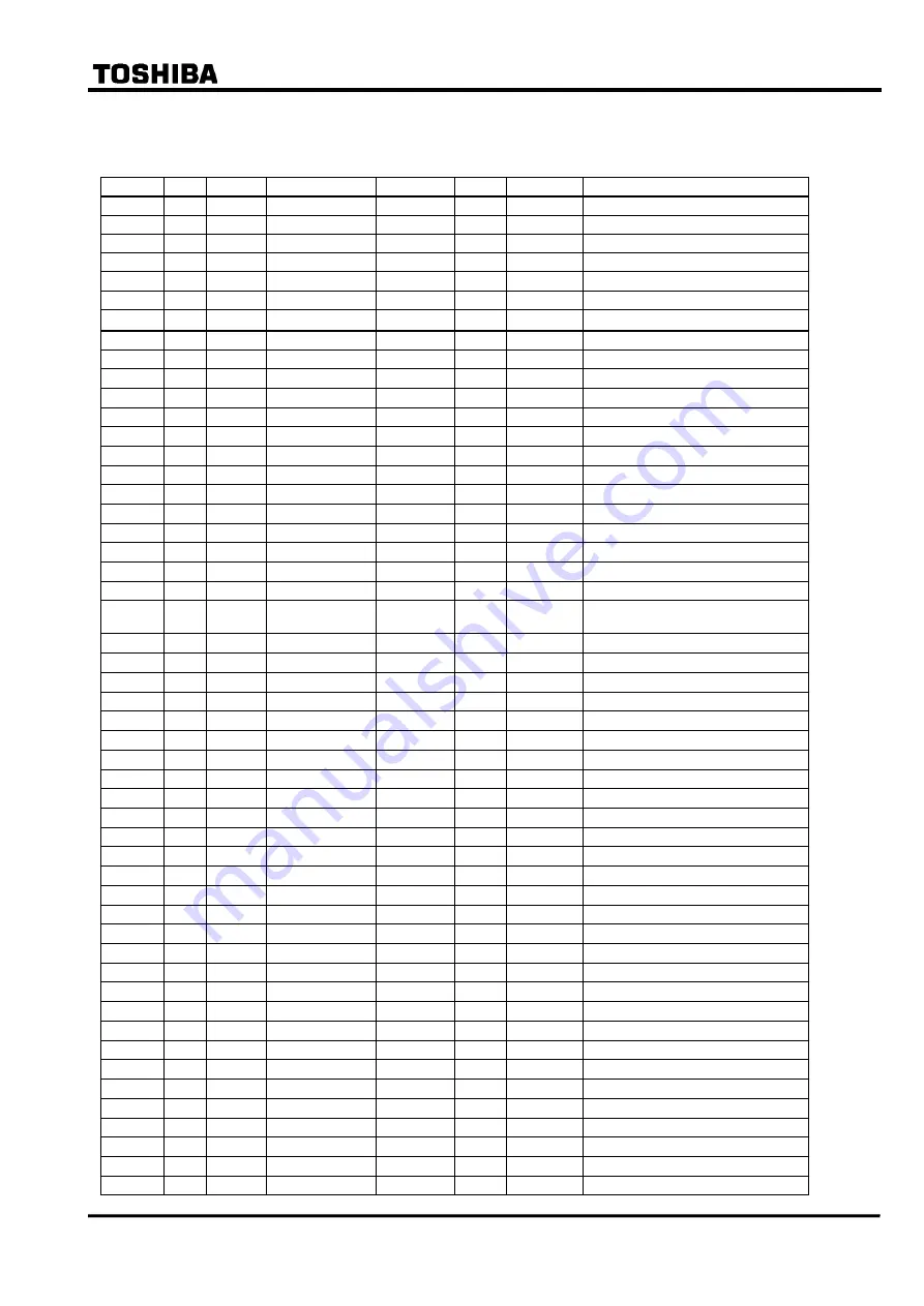
(2) Modbus address map
Address
Hex
Function
Contents
Unit
LSB
bit
Control
512
200
1,2,5
Control start
1027
403
1,2,5
Time trigger
1028
404
1,2,5
Reset Trip LED
Signal List
4608
1200
1,2
signal list#0
4609
1201
1,2
signal list#1
4610
1202
1,2
signal list#2
・・・
・・・
・・・
・・・
7679
1DFF
1,2
signal list#3071
Alias (bit)
7680
1E00
2
alias coil #1
7681
1E01
2
alias coil #2
・・・
・・・
・・・
・・・
7711
1E1F
2
alias coil #32
Metering
8192
2000
4
V
V
0.007
8193
2001
4
(Phase)
degree
0.01
8194
2002
4
Ia1
A
0.001xIN
8195
2003
4
(Phase)
degree
0.01
8196
2004
4
Ib1
A
0.001xIN
8197
2005
4
(Phase)
degree
0.01
8198
2006
4
Ic1
A
0.001xIN
8199
2007
4
(Phase)
degree
0.01
8200
2008
4
Ia2
A
0.001xIN
8201
2009
4
(Phase)
degree
0.01
8202
200A
4
Ib2
A
0.001xIN
8203
200B
4
(Phase)
degree
0.01
8204
200C
4
Ic2
A
0.001xIN
8205
200D
4
(Phase)
degree
0.01
8206
200E
4
Ia3
A
0.001xIN
8207
200F
4
(Phase)
degree
0.01
8208
2010
4
Ib3
A
0.001xIN
8209
2011
4
(Phase)
degree
0.01
8210
2012
4
Ic3
A
0.001xIN
8211
2013
4
(Phase)
degree
0.01
8218
201A
4
I11
A
0.001xIN
8219
201B
4
(Phase)
degree
0.01
8220
201C
4
I12
A
0.001xIN
8221
201D
4
(Phase)
degree
0.01
8222
201E
4
I13
A
0.001xIN
8223
201F
4
(Phase)
degree
0.01
8226
2022
4
I21
A
0.001xIN
8227
2023
4
(Phase)
degree
0.01
8228
2024
4
I22
A
0.001xIN
8229
2025
4
(Phase)
degree
0.01
Summary of Contents for GRT100 Series
Page 142: ... 141 6 F 2 S 0 7 8 9 Appendix A Block Diagram ...
Page 144: ... 143 6 F 2 S 0 7 8 9 Appendix B Signal List ...
Page 159: ... 158 6 F 2 S 0 7 8 9 ...
Page 160: ... 159 6 F 2 S 0 7 8 9 Appendix C Variable Timer List ...
Page 162: ... 161 6 F 2 S 0 7 8 9 Appendix D Binary Output Default Setting List ...
Page 165: ... 164 6 F 2 S 0 7 8 9 ...
Page 166: ... 165 6 F 2 S 0 7 8 9 Appendix E Details of Relay Menu and LCD and Button Operation ...
Page 174: ... 173 6 F 2 S 0 7 8 9 Appendix F Case Outline Flush Mount Type Rack Mount Type ...
Page 179: ... 178 6 F 2 S 0 7 8 9 ...
Page 180: ... 179 6 F 2 S 0 7 8 9 Appendix G External Connections ...
Page 185: ... 184 6 F 2 S 0 7 8 9 ...
Page 200: ... 199 6 F 2 S 0 7 8 9 ...
Page 201: ... 200 6 F 2 S 0 7 8 9 Appendix J Return Repair Form ...
Page 205: ... 204 6 F 2 S 0 7 8 9 Customer Name Company Name Address Telephone No Facsimile No Signature ...
Page 206: ... 205 6 F 2 S 0 7 8 9 ...
Page 207: ... 206 6 F 2 S 0 7 8 9 Appendix K Technical Data ...
Page 220: ... 219 6 F 2 S 0 7 8 9 ...
Page 221: ... 220 6 F 2 S 0 7 8 9 Appendix M Symbols Used in Scheme Logic ...
Page 224: ... 223 6 F 2 S 0 7 8 9 ...
Page 225: ... 224 6 F 2 S 0 7 8 9 Appendix N Implementation of Thermal Model to IEC60255 8 ...
Page 228: ... 227 6 F 2 S 0 7 8 9 ...
Page 229: ... 228 6 F 2 S 0 7 8 9 Appendix O IEC60870 5 103 Interoperability and Troubleshooting ...
Page 241: ... 240 6 F 2 S 0 7 8 9 Appendix P Modbus Interoperability ...
Page 255: ... 254 6 F 2 S 0 7 8 9 ...
Page 256: ... 255 6 F 2 S 0 7 8 9 Appendix Q Inverse Time Characteristics ...
Page 259: ... 258 6 F 2 S 0 7 8 9 ...
Page 260: ... 259 6 F 2 S 0 7 8 9 Appendix R Failed Module Tracing and Replacement ...
Page 266: ... 265 6 F 2 S 0 7 8 9 Appendix S Ordering ...
Page 269: ... 268 6 F 2 S 0 7 8 9 3 1 Oct 2 2017 Republished under spin off company ...
Page 270: ......


