260
6
F
2
S
0
7
8
9
1.
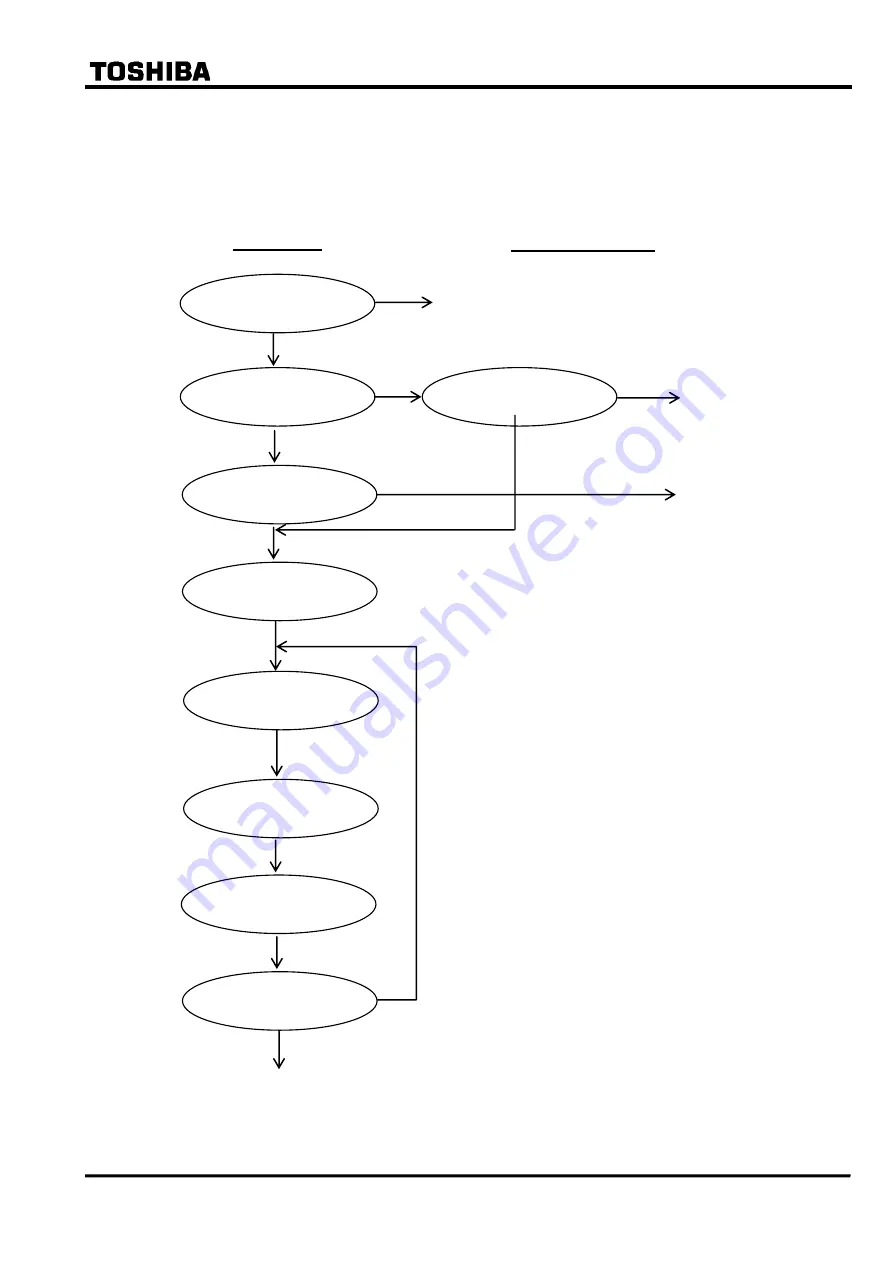
Failed module tracing and its replacement
If the
“
ALARM
”
LED is ON, the following procedure is recommended. If not repaired, contact
the vendor.
“ALARM” LED ON?
Any LCD messages?
Locate the failed module.
Module replacement
If both
“IN SERVICE” LED and “ALARM” LED are
OFF, check the followings.
Check: Is DC supply voltage available with the correct
polarity and of adequate magnitude, and
connected to the correct terminals?
No
No failure
Locate the failed module referring to Table Q-1.
Caution: Check that the replacement module has an
identical module name (VCT, SPM, IO1,
IO2, etc.) and hardware type-form as the
failed module. Furthermore, the SPM
module must have the same software
name and version. Refer to Section
4.2.5.1.
Countermeasure
As shown in the table, some of the messages cannot
identify the fault location definitely but suggest plural
possible failure locations. In these cases, the failure
location is identified by replacing the suggested failed
modules with spare modules one by one until the
"ALARM" LED is turned off.
DC supply
“OFF”
DC supply
“ON”
“ALARM” LED OFF?
No
Contact the vendor.
End
No
Not displayed
Press [VIEW] key
Contact the vendor.
Not displayed
Press [VIEW] key
Yes
Yes
Procedure
Summary of Contents for GRT100 Series
Page 142: ... 141 6 F 2 S 0 7 8 9 Appendix A Block Diagram ...
Page 144: ... 143 6 F 2 S 0 7 8 9 Appendix B Signal List ...
Page 159: ... 158 6 F 2 S 0 7 8 9 ...
Page 160: ... 159 6 F 2 S 0 7 8 9 Appendix C Variable Timer List ...
Page 162: ... 161 6 F 2 S 0 7 8 9 Appendix D Binary Output Default Setting List ...
Page 165: ... 164 6 F 2 S 0 7 8 9 ...
Page 166: ... 165 6 F 2 S 0 7 8 9 Appendix E Details of Relay Menu and LCD and Button Operation ...
Page 174: ... 173 6 F 2 S 0 7 8 9 Appendix F Case Outline Flush Mount Type Rack Mount Type ...
Page 179: ... 178 6 F 2 S 0 7 8 9 ...
Page 180: ... 179 6 F 2 S 0 7 8 9 Appendix G External Connections ...
Page 185: ... 184 6 F 2 S 0 7 8 9 ...
Page 200: ... 199 6 F 2 S 0 7 8 9 ...
Page 201: ... 200 6 F 2 S 0 7 8 9 Appendix J Return Repair Form ...
Page 205: ... 204 6 F 2 S 0 7 8 9 Customer Name Company Name Address Telephone No Facsimile No Signature ...
Page 206: ... 205 6 F 2 S 0 7 8 9 ...
Page 207: ... 206 6 F 2 S 0 7 8 9 Appendix K Technical Data ...
Page 220: ... 219 6 F 2 S 0 7 8 9 ...
Page 221: ... 220 6 F 2 S 0 7 8 9 Appendix M Symbols Used in Scheme Logic ...
Page 224: ... 223 6 F 2 S 0 7 8 9 ...
Page 225: ... 224 6 F 2 S 0 7 8 9 Appendix N Implementation of Thermal Model to IEC60255 8 ...
Page 228: ... 227 6 F 2 S 0 7 8 9 ...
Page 229: ... 228 6 F 2 S 0 7 8 9 Appendix O IEC60870 5 103 Interoperability and Troubleshooting ...
Page 241: ... 240 6 F 2 S 0 7 8 9 Appendix P Modbus Interoperability ...
Page 255: ... 254 6 F 2 S 0 7 8 9 ...
Page 256: ... 255 6 F 2 S 0 7 8 9 Appendix Q Inverse Time Characteristics ...
Page 259: ... 258 6 F 2 S 0 7 8 9 ...
Page 260: ... 259 6 F 2 S 0 7 8 9 Appendix R Failed Module Tracing and Replacement ...
Page 266: ... 265 6 F 2 S 0 7 8 9 Appendix S Ordering ...
Page 269: ... 268 6 F 2 S 0 7 8 9 3 1 Oct 2 2017 Republished under spin off company ...
Page 270: ......


