76
6
F
2
S
0
7
8
9
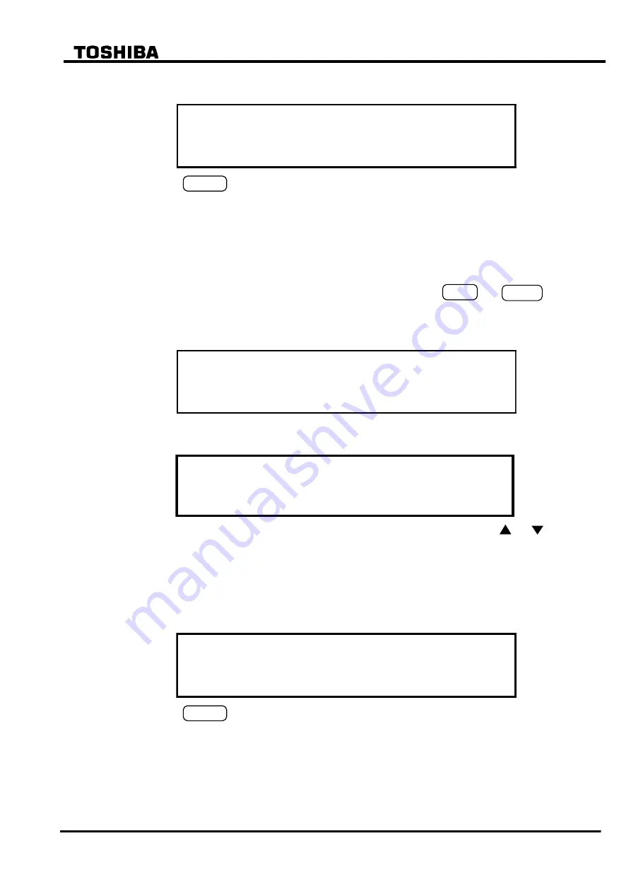
Select 2 (= Clear) to display the following confirmation screen.
/ 2
F a u l t
r e c o r d
C l e a r
a l l
f a u l t
r e c o r d s ?
E N T E R = Y e s
C A N C E L = N o
Press the
ENTER
(= Yes) key to clear all the fault records stored in non-volatile memory.
If all fault records have been cleared, the "Latest fault" screen of the digest screens is not
displayed.
4.2.3.2 Displaying Event Records
To display events records, do the following:
Open the top "MENU" screen by pressing any keys other than the
VIEW
and
RESET
keys.
Select 1 (= Record) to display the "Record" sub-menu.
Select 2 (= Event record) to display the "Event record" screen.
1 =
a
/ 2
R e c o r
i s l
D
p
2 = C l e a r
v e t
E
n
d
y
Select 1 (= Display) to display the events with date and time from the top in new-to-old
sequence.
/ 3
E v e n t
r e c o r d
2 / 4 8
1 6 / O c t / 1 9 9 8
2 3 : 1 8 : 0 4 . 2 9 4
T r i p
1 6 / O c t / 1 9 9 8
2 3 : 1 8 : 0 3 . 9 1 3
1 2 / F e b / 1 9 9 8
0 3 : 5 1 : 3 7 . 6 2 2
R l y .
e
s
t
O f f
T r i p
O n
c h a
g
n
e
The lines which are not displayed in the window can be displayed by pressing the and keys.
To clear all the event records, do the following:
Open the "Record" sub-menu.
Select 2 (Event record) to display the "Event record" screen.
Select 2 (= Clear) to display the following confirmation screen.
/ 2
E v e n t
r e c o r d
C l e a r
a l l
e v e n t
r e c o r d s ?
E N T E R = Y e s
C A N C E L = N o
Press the
ENTER
(= Yes) key to clear all the event records stored in non-volatile memory.
4.2.3.3 Displaying Disturbance Records
Details of the disturbance records can be displayed on the PC screen only (*); the LCD displays
only the recorded date and time for all disturbances stored in the relay. To display them, do the
following:
(*) For the display on the PC screen, refer to RSM100 manual.
Summary of Contents for GRT100 Series
Page 142: ... 141 6 F 2 S 0 7 8 9 Appendix A Block Diagram ...
Page 144: ... 143 6 F 2 S 0 7 8 9 Appendix B Signal List ...
Page 159: ... 158 6 F 2 S 0 7 8 9 ...
Page 160: ... 159 6 F 2 S 0 7 8 9 Appendix C Variable Timer List ...
Page 162: ... 161 6 F 2 S 0 7 8 9 Appendix D Binary Output Default Setting List ...
Page 165: ... 164 6 F 2 S 0 7 8 9 ...
Page 166: ... 165 6 F 2 S 0 7 8 9 Appendix E Details of Relay Menu and LCD and Button Operation ...
Page 174: ... 173 6 F 2 S 0 7 8 9 Appendix F Case Outline Flush Mount Type Rack Mount Type ...
Page 179: ... 178 6 F 2 S 0 7 8 9 ...
Page 180: ... 179 6 F 2 S 0 7 8 9 Appendix G External Connections ...
Page 185: ... 184 6 F 2 S 0 7 8 9 ...
Page 200: ... 199 6 F 2 S 0 7 8 9 ...
Page 201: ... 200 6 F 2 S 0 7 8 9 Appendix J Return Repair Form ...
Page 205: ... 204 6 F 2 S 0 7 8 9 Customer Name Company Name Address Telephone No Facsimile No Signature ...
Page 206: ... 205 6 F 2 S 0 7 8 9 ...
Page 207: ... 206 6 F 2 S 0 7 8 9 Appendix K Technical Data ...
Page 220: ... 219 6 F 2 S 0 7 8 9 ...
Page 221: ... 220 6 F 2 S 0 7 8 9 Appendix M Symbols Used in Scheme Logic ...
Page 224: ... 223 6 F 2 S 0 7 8 9 ...
Page 225: ... 224 6 F 2 S 0 7 8 9 Appendix N Implementation of Thermal Model to IEC60255 8 ...
Page 228: ... 227 6 F 2 S 0 7 8 9 ...
Page 229: ... 228 6 F 2 S 0 7 8 9 Appendix O IEC60870 5 103 Interoperability and Troubleshooting ...
Page 241: ... 240 6 F 2 S 0 7 8 9 Appendix P Modbus Interoperability ...
Page 255: ... 254 6 F 2 S 0 7 8 9 ...
Page 256: ... 255 6 F 2 S 0 7 8 9 Appendix Q Inverse Time Characteristics ...
Page 259: ... 258 6 F 2 S 0 7 8 9 ...
Page 260: ... 259 6 F 2 S 0 7 8 9 Appendix R Failed Module Tracing and Replacement ...
Page 266: ... 265 6 F 2 S 0 7 8 9 Appendix S Ordering ...
Page 269: ... 268 6 F 2 S 0 7 8 9 3 1 Oct 2 2017 Republished under spin off company ...
Page 270: ......


