12
6
F
2
S
0
7
8
9
2.3 Current Differential Protection
2.3.1 Differential Scheme
Current differential protection DIFT provides an overall transformer protection deriving phase
current from each transformer winding, calculating the differential current on a per phase basis
and detecting phase-to-phase and phase-to-earth faults.
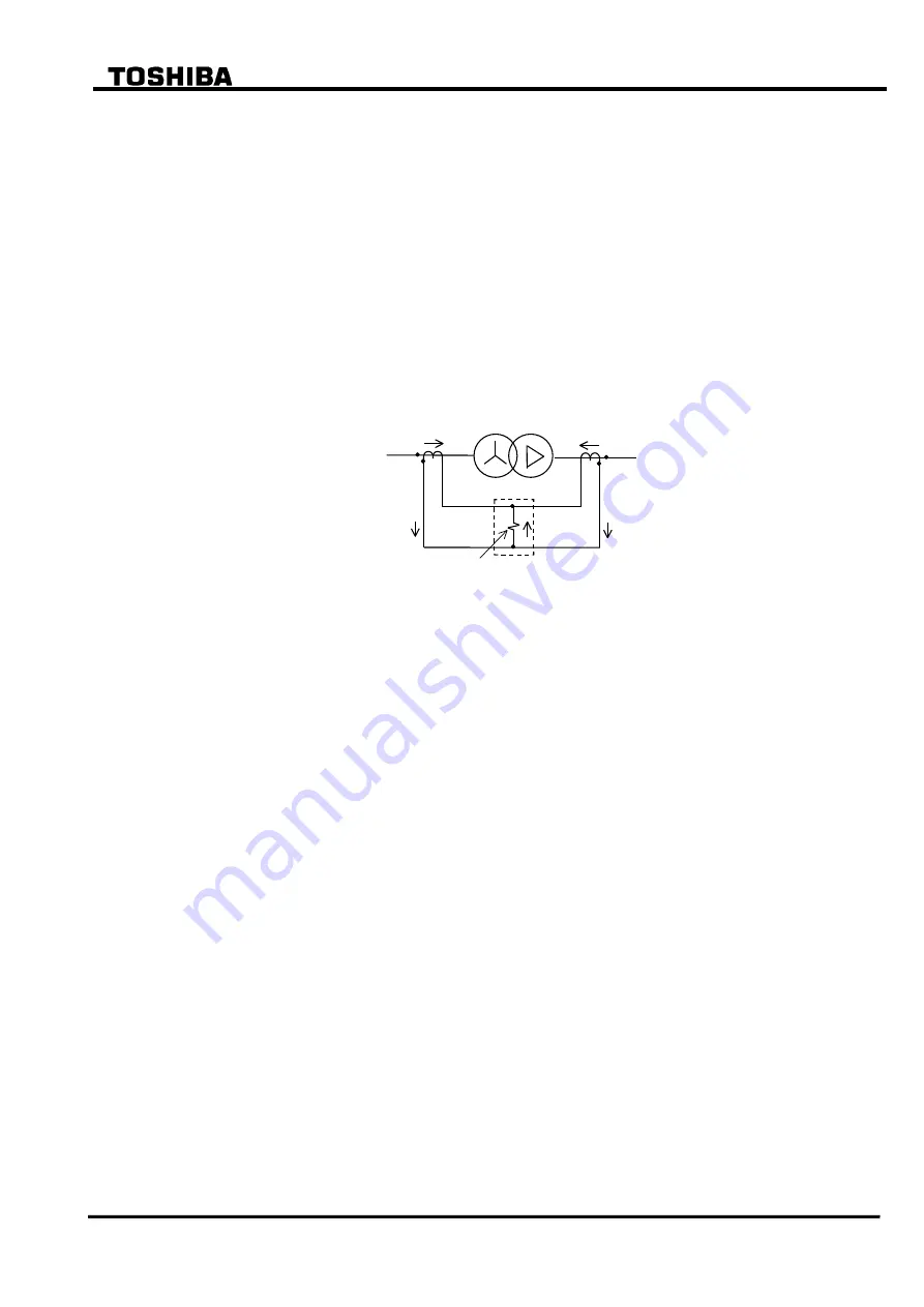
The current differential protection is based on Kirchhoff’s first law that the vector summation of
all currents flowing into a protected zone must be zero. Figure 2.3.1 shows the principle of
current differential protection. Differential current (id) is the vector summation of all terminal
current of the transformer. The differential current (id=i1+i2) is zero because the current (i1)
equals current (
i2) during a load condition or an external fault. During an internal fault, the
differential current (id) is not zero because the current (i1) does not equal to the current (
i2), and
the DIFT operates.
DIFT
I1
I2
i1
i2
id=i1+i2
Differential current
detection
Transformer
Primary
Secondary
Figure 2.3.1 Current Differential Protection
Scheme logic
Figure 2.3.2 shows the scheme logic of current differential protection. Current differential
element DIFT comprises sub-elements HOC, DIF, 2F and 5F which operate for the differential
current on a per phase basis.
Note:
For the symbols used in the scheme logic, see Appendix M.
HOC is a high-set overcurrent element operating for the differential current. It provides
high-speed protection for heavy internal faults.
DIF is a percentage restraining element and has dual restraining characteristics, a weak restraint
in the small current region and a strong restraint in the large current region, to cope with
erroneous differential current which may be caused due to output imbalance of CTs in case of an
external fault. (For the characteristics, see Section 2.11.)
DIF output signal can be blocked when 2F or 5F element detects second harmonic inrush current
during transformer energization or fifth harmonic components during transformer
over-excitation. The blocking is enabled by setting the scheme switch [2F-LOCK] or [5F-LOCK]
to “ON”. The following two blocking scheme is selectable by the scheme switch [DIFTPMD].
(For details, see Table 2.3.1.)
“3POR”: When any one phase of 2F or 5F element operates, the trip by DIF element is
blocked in all three phases. The “3POR” is recommended for the transformers
whose second harmonic component may be low because its block function is
stronger than that of the “2PAND” below.
“2PAND”: Even if 2F or 5F element operates, the trip by DIF element is allowed when any
two phases or more of DIF element operate. The “2PAND” is recommended for
the transformers whose second harmonic component is higher. The relay does
not operate due to inruch current so long as second harmonic is detected by two
Summary of Contents for GRT100 Series
Page 142: ... 141 6 F 2 S 0 7 8 9 Appendix A Block Diagram ...
Page 144: ... 143 6 F 2 S 0 7 8 9 Appendix B Signal List ...
Page 159: ... 158 6 F 2 S 0 7 8 9 ...
Page 160: ... 159 6 F 2 S 0 7 8 9 Appendix C Variable Timer List ...
Page 162: ... 161 6 F 2 S 0 7 8 9 Appendix D Binary Output Default Setting List ...
Page 165: ... 164 6 F 2 S 0 7 8 9 ...
Page 166: ... 165 6 F 2 S 0 7 8 9 Appendix E Details of Relay Menu and LCD and Button Operation ...
Page 174: ... 173 6 F 2 S 0 7 8 9 Appendix F Case Outline Flush Mount Type Rack Mount Type ...
Page 179: ... 178 6 F 2 S 0 7 8 9 ...
Page 180: ... 179 6 F 2 S 0 7 8 9 Appendix G External Connections ...
Page 185: ... 184 6 F 2 S 0 7 8 9 ...
Page 200: ... 199 6 F 2 S 0 7 8 9 ...
Page 201: ... 200 6 F 2 S 0 7 8 9 Appendix J Return Repair Form ...
Page 205: ... 204 6 F 2 S 0 7 8 9 Customer Name Company Name Address Telephone No Facsimile No Signature ...
Page 206: ... 205 6 F 2 S 0 7 8 9 ...
Page 207: ... 206 6 F 2 S 0 7 8 9 Appendix K Technical Data ...
Page 220: ... 219 6 F 2 S 0 7 8 9 ...
Page 221: ... 220 6 F 2 S 0 7 8 9 Appendix M Symbols Used in Scheme Logic ...
Page 224: ... 223 6 F 2 S 0 7 8 9 ...
Page 225: ... 224 6 F 2 S 0 7 8 9 Appendix N Implementation of Thermal Model to IEC60255 8 ...
Page 228: ... 227 6 F 2 S 0 7 8 9 ...
Page 229: ... 228 6 F 2 S 0 7 8 9 Appendix O IEC60870 5 103 Interoperability and Troubleshooting ...
Page 241: ... 240 6 F 2 S 0 7 8 9 Appendix P Modbus Interoperability ...
Page 255: ... 254 6 F 2 S 0 7 8 9 ...
Page 256: ... 255 6 F 2 S 0 7 8 9 Appendix Q Inverse Time Characteristics ...
Page 259: ... 258 6 F 2 S 0 7 8 9 ...
Page 260: ... 259 6 F 2 S 0 7 8 9 Appendix R Failed Module Tracing and Replacement ...
Page 266: ... 265 6 F 2 S 0 7 8 9 Appendix S Ordering ...
Page 269: ... 268 6 F 2 S 0 7 8 9 3 1 Oct 2 2017 Republished under spin off company ...
Page 270: ......


