GRZ100
10
Calendar and Time
The calendar and time are provided for the time-tagging of
recorded data. Synchronisation with GPS (Global
Positioning System) is achieved via the IRIG-B port.
USER INTERFACE
Relay Front Panel
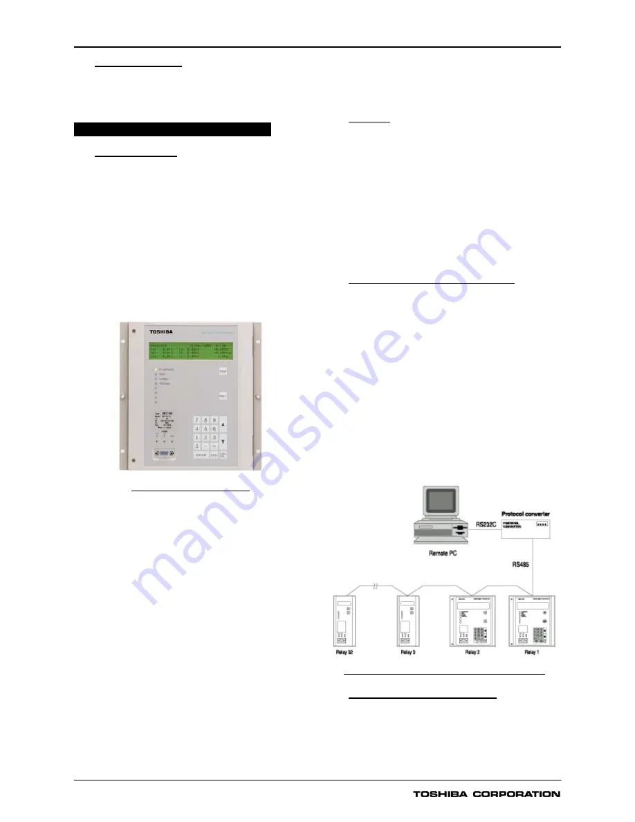
The relay front panel incorporates the following user
interfaces. Setting the relay and viewing stored data are
possible using the Liquid Crystal Display (LCD) and
operation keys.
- 40 character, four line LCD with back light
- Eight Light Emitting Diodes (LED) including four that are
configurable
- Operation keys
- RS232C port
- Monitoring jacks
Figure 13 shows the relay front panel.
Figure 13 Relay front panel
The following items can be displayed on the LCD.
- Setting
- Metering
- Event records
- Fault records
- The number of disturbance records
- Fault location
- Any failure code detected by the automatic supervision
Password protection can be provided from the setting menu
on the LCD to provide security for relay setting changes.
After the password has been set, the password must be
entered to access the setting menu from a local or remote PC
as well as on the LCD.
The contents of metering, fault records, and relay failures
can be monitored by pressing the VIEW key. The VIEW key
can be pressed without removing the relay front cover.
Arbitrary signals can be assigned to the four user
configurable LEDs.
Two monitoring jacks are operable when the test mode is
selected in the LCD window. An oscilloscope can be
connected to the relay through these jacks. Selection of
output signals on the monitoring jacks can be set from the
menu.
Local PC
The user can communicate with the GRZ100 from a local
PC via the RS232C port on the relay fascia. The following data
can be viewed or analysed on the local PC with RSM100
software.
- Setting
- Metering
- Event records
- Fault records
- Disturbance records
- Fault location
Relay Setting and Monitoring (RSM)
GRZ100 can be connected to the RSM system via the
RS485 interface at the rear of the relay. The user can
operate the relay from a remote PC in the same way as
from a local PC.
Figure 14 shows the configuration of the RSM system via
the protocol converter G1PR2 (option). The G1PR2 can be
provided with maximum 8 ports and each port supports 32
relays addressing.
A maximum of 32 x 8 relays can be connected to the
remote PC in multi-drop mode, via the protocol converter.
The RSM100 software is also used to communicate with the
relay and to view or analyze disturbance records on the
remote PC.
The data transmission rate between relays and the protocol
converter is 64kbps.
G1PR2
Figure 14 Relay setting and monitoring system
IEC60870-5-103 Communication
The relay can support the IEC60870-5-103 communication
protocol. This protocol is mainly used when the relay
communicates with a control system and is used to transfer
the measurand data, status data and general command
from the relay to the control system.


