background image

8

90°

Die

Pipe

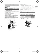
Refrigerant Piping Connection

1.  Cut the pipe with a pipe cutter.

2. Insert a 

fl

 are nut into the pipe and 

fl

 are the pipe.

• 

Projection margin in 

fl

 aring : A (Unit : mm)

Rigid (clutch type)

Imperial (wing nut type)

Outer dia. of copper pipe

R410A

Ø6.35

1.5 to 2.0

Ø12.70

2.0 to 2.5

Outer dia.

of copper pipe

R410A tool used

Conventional tool 

used

Ø6.35

0 to 0.5

1.0 to 1.5

Ø12.70

0 to 0.5

1.0 to 1.5

   Flaring

Obliquity

Roughness

Warp 

Installation Place

•  A place which provides the spaces around the outdoor unit as shown in 

the diagram

•  A place which can bear the weight of the outdoor unit and does not allow 

an increase in noise level and vibration

•  A place where the operation noise and discharged air do not disturb your 

neighbors

•  A place which is not exposed to a strong wind
•  A place free of a leakage of combustible gases
•  A place which does not block a passage
•  When the outdoor unit is to be installed in an elevated position, be sure to 

secure its feet.

•  A place where the drain water does not raise any problems

CAUTION

1.  Install the outdoor unit without anything blocking the air discharging.
2.  When the outdoor unit is installed in a place always exposed to strong 

wind like a coast or on a high storey of a building, secure the normal fan 
operation using a duct or a windshield.

3.  In particularly windy areas, install the unit such as to avoid admission of 

wind.

4.  Installation in the following places may result in trouble.

Do not install the unit in such places.
•  A place full of machine oil
•  A saline-place such as the coast
•  A place full of sul

fi

 de gas

•  A place where high-frequency 

waves are likely to be generated 
as from audio equipment, welders, 
and medical equipment

Strong 

wind

Incused line

Flare at hydro 
unit side

Flare at outdoor 
unit side

Flare nut

Half union

Externally
threaded side

Internally
threaded side

Use a wrench to secure.

Use a torque wrench to tighten.

CAUTION

Align the centers of the connecting pipes and tighten the 

fl

 are nut as far as 

possible with your 

fi

 ngers. Then tighten the nut with a spanner and torque 

wrench as shown in the 

fi

 gure.


Tightening connection

Do not apply excess torque. Otherwise, the nut may crack depending on 
the conditions.

(Unit : N·m)

Outer dia. of copper pipe 

Tightening torque

Ø6.35 mm

14 to 18 (1.4 to 1.8 kgf·m)

Ø12.70 mm

50 to 62 (5.0 to 6.2 kgf·m)

• 

Tightening torque of 

fl

 are pipe connections

The operating pressure of R410A 
is higher than that of R22 (approx. 
1.6 times). It is therefore necessary 
to 

fi

 rmly tighten the 

fl

 are pipe 

connecting sections (which connect 
the hydro and outdoor units) up to the 
speci

fi

 ed tightening torque. Incorrect 

connections may cause not only a 
gas leakage, but also damage to the 
refrigeration cycle.

1.  How to shape the pipes 

Shape the pipes along the incused line on
the outdoor unit.

2. How to 

fi

 t position of the pipes

Put the edges of the pipes to the place with
a distance of 85 mm from the incused line.

   Shaping pipes

Refrigerant pipe
H: max. ±10 m (above / below)
L:  max. 15 m, min 5 m

15 m chargeless

Hydro Unit

Outdoor unit

15 m chargeless

L

H

   Refrigerant pipe length

01_1120551201-1 EN.indd   8

01_1120551201-1 EN.indd   8

5/18/2560 BE 3:12 PM

5/18/2560 BE   3:12 PM

Summary of Contents for HWS-455H-E

Page 1: ...Outdoor unit HWS 455H E AIR TO WATER HEAT PUMP INSTALLATION MANUAL ENGLISH ...

Page 2: ...Refrigerant Piping Connection Evacuating ELECTRICAL WORKS Wiring Connection Power Supply and Connecting Cable Connection Power supply input Wiring Diagram OTHERS Gas Leak Test Earthing Finishing Test run Annual maintenance Air to water heat pump operating conditions CONTENTS EN 1 7 7 7 8 8 9 10 10 10 10 11 11 11 11 11 11 11 ...

Page 3: ...se of this unit can result in a high possibility of severe injury 1 or death WARNING It indicates that incorrect use of this unit may cause severe injury or death CAUTION It indicates that incorrect use of this unit may cause personal injury 2 or property damage 3 1 A severe injury refers to blindness injury burns hot or cold electrical shock bone fracture or poisoning that leaves aftereffects and...

Page 4: ...e sizes of charging port connecting sections on the main unit are different from those for the conventional refrigerant and different size tools are also required For connecting pipes use new and clean piping materials with high pressure withstand capabilities designed for R410A only and ensure that water or dust does not enter Moreover do not use any existing piping as its pressure withstand may ...

Page 5: ... RADIATORS HEATERS FURNACE STOVES ETC WHEN MOVING THE AIR TO WATER HEAT PUMP FOR INSTALLING IT IN ANOTHER PLACE AGAIN BE VERY CAREFUL NOT TO GET THE SPECIFIED REFRIGERANT R410A WITH ANY OTHER GASEOUS BODY INTO THE REFRIGERATION CYCLE IF AIR OR ANY OTHER GAS IS MIXED IN THE REFRIGERANT THE GAS PRESSURE IN THE REFRIGERATION CYCLE BECOMES ABNORMALLY HIGH AND IT RESULTINGLY CAUSES BURST OF THE PIPE AN...

Page 6: ...he hydro outdoor units Midway connection stranded wire and single wire connections are not allowed Improper connection or fixing may cause a fire Wiring between the hydro unit and outdoor units must be well shaped so that the cover can be firmly placed Improper cover installation may cause increased heat fire or electrical shock at the terminal area Be sure to use only approved accessories or the ...

Page 7: ...air absorbed and abnormal high pressure inside the refrigeration cycle and resulting burst or injury Do not modify the power cable connect the cable midway or use a multiple outlet extension cable Doing so may cause contact failure insulation failure or excess current resulting in fire or electrical shock Do not use any refrigerant different from the one specified for complement or replacement Oth...

Page 8: ...harged Improper drainage can result in water leakage causing water damage to furniture Tighten the flare nut with a torque wrench using the prescribed method Do not apply excess torque Otherwise the nut may crack after a long period of usage and it may cause the leakage of refrigerant Wear gloves heavy gloves such as cotton gloves for installation work Failure to do so may cause personal injury wh...

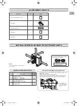
Page 9: ...ION DIAGRAM OF OUTDOOR UNITS INSTALLATION DIAGRAM OF OUTDOOR UNITS Part code Parts name Q ty A Refrigerant piping Liquid side Ø6 35 mm Gas side Ø12 7 mm One each B Pipe insulating material polyethylene foam 6 mm thick 1 C Putty PVC tapes One each Optional Installation Parts 600 mm or more 100 mm or more 100 mm or more 600 mm or more 600 mm or more Remark Some pictures might be different from the a...

Page 10: ... A place full of machine oil A saline place such as the coast A place full of sulfide gas A place where high frequency waves are likely to be generated as from audio equipment welders and medical equipment Strong wind Incused line Flare at hydro unit side Flare at outdoor unit side Flare nut Half union Externally threaded side Internally threaded side Use a wrench to secure Use a torque wrench to ...

Page 11: ...d liquid sides 7 Remove the charging hose from the service port 8 Securely tighten the caps on the packed valves Using a vacuum pump Packed valve at liquid side Service port Valve core Setting pin Packed valve at gas side Vacuum pump Vacuum pump adapter for counter flow prevention For R410A only Charge hose For R410A only Handle Hi Keep full closed Manifold valve Pressure gauge Compound pressure g...

Page 12: ... Block 0 1 0 1 0 1 0 1 30 30 40 40 L N 1 2 3 1 2 3 L N Connecting cable Earth line Earth line Connecting cable Connecting cable connect to terminal block 1 2 3 Power supply terminal block L N Power cord Power cord Terminal block CAUTION 1 The power supply must be same as the rated of air to water heat pump 2 Prepare the power source for exclusive use with air to water heat pump 3 Circuit breaker m...

Page 13: ...d which may damage the compressor or other components If there is a leak at a connection air can be sucked in and the internal pressure further increases which may cause a burst or injury Operate the air to water heat pump in the correct procedure as specified in the Owner s Manual Please refer to the Hydro unit installation manual for the detail of the test run For an air to water heat pump syste...

Page 14: ......

Reviews: