background image


Document: VF010H03 Rev. 5 


INSTRUCTION MANUAL 


INSTALLATION – OPERATION – MAINTENANCE 


JK Series 

400 Ampere Medium Voltage Controllers 

Fixed Type 

7.2kV Maximum 


Issued: 9/19  

Summary of Contents for JK400 Series

Page 1: ...Document VF010H03 Rev 5 INSTRUCTION MANUAL INSTALLATION OPERATION MAINTENANCE JK Series 400 Ampere Medium Voltage Controllers Fixed Type 7 2kV Maximum Issued 9 19 ...

Page 2: ...Basic Installation and Operation Guide JK Series 400 Series Fixed Controllers ...

Page 3: ...tements contained herein do not create new warranties or modify the existing warranty Any electrical or mechanical modifications to this equipment without the prior written consent of Toshiba International Corporation may void all warranties or other safety certifications Unauthorized modifications may also result in safety hazard or equipment damage Misuse of this equipment could result in injury...

Page 4: ...available for reference and review Dimensions shown in the manual are in imperial units and or the metric equivalent Connection drawings within this document convey the typical topology of the JK 400 controller Because of our commitment to continuous improvement Toshiba International Corporation reserves the right without prior notice to update information make product changes or to discontinue an...

Page 5: ...nternational Corporation 13131 West Little York Road Houston Texas 77041 9990 For further information on Toshiba International Corporation s products and services please visit our website at www toshiba com tic TOSHIBA INTERNATIONAL CORPORATION JK Series Controller Complete the following information and retain for your records Model Number __________________________________________________________...

Page 6: ... used in this manual they will be followed by important safety information that must be carefully followed The word DANGER preceded by the safety alert symbol indicates that an imminently hazardous situation exists that if not avoided or if instructions are not followed precisely will result in serious injury to personnel or loss of life The word WARNING preceded by the safety alert symbol indicat...

Page 7: ...ion and maintenance shall be performed by Qualified Personnel ONLY A Qualified Person is one that has the skills and knowledge relating to the construction installation operation and maintenance of the electrical equipment and has received safety training on the hazards involved Refer to the latest edition of NFPA 70E for additional safety requirements Qualified Personnel shall Have carefully read...

Page 8: ...y be required after moving the equipment Contact your Toshiba Customer Support Center to report discrepancies or for assistance if required Handling and Storage Use proper lifting techniques when moving the equipment including properly sizing up the load getting assistance and using a forklift if required Store in a well ventilated location preferably in the original packaging if the equipment wil...

Page 9: ...Basic Installation and Operation Guide JK 400 Series Fixed Controllers TOSHIBA ...

Page 10: ...ections 5 Medium Voltage Power Connections 7 Incoming Line 9 Load Connections 9 Power Fuse Cartridge 10 PRE ENERGIZATION CHECK 11 General 11 Wiring Check 12 Device Mechanism Checks 13 Electrical Checks 14 GENERAL DESCRIPTION 15 Construction 15 Controller Compartment 16 Isolation Switch 16 Vacuum Contactor 17 Outgoing Load Connections 17 Control Power Potential Transformers 18 Operating Handle 19 I...

Page 11: ...ral Inspection 29 Electrical Joints 29 Power Fuses 30 Vacuum Contactor 30 Isolation Switch 31 Switch Handle Mechanism 32 Interlocks 33 Control Power Potential Transformers 33 MAINTENANCE AFTER A FAULT CONDITION 34 Enclosure 34 Isolation Switch 34 Fuse Mounting 34 Terminals and Internal Conductors 34 Overload Relay 34 Vacuum Contactor 34 Return to Service 34 ...

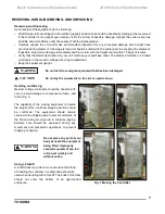
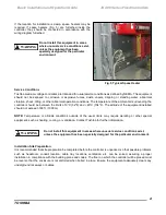
Page 12: ...ocated on stickers in the medium voltage incoming compartment Keep the equipment upright Do not install or energize equipment that has been damaged Do not lay the equipment on its side or upside down Handling and Moving Medium voltage controllers should be handled with care to avoid damage to components frame and finish Fig 1 The capability of the moving equipment to handle the weight of the contr...

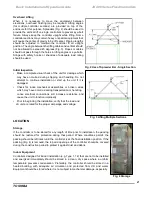
Page 13: ...to continue installation or start up the unit if it is damaged Check for loose mechanical assemblies or broken wires which may have occurred during transportation or handling Loose electrical connections will increase resistance and cause the unit to function improperly Prior to beginning the installation verify that the load and JK unit are rated for the proper amperage and voltage Fig 3 Lifting ...

Page 14: ...or evidence of physical damage corrosion or other deterioration Do not install equipment found to have damage or deterioration that could affect the unit performance INSTALLATION Rating Verification Prior To Installation The maximum fault capability of the power system at the point of installation should be verified and must not exceed the short circuit rating of the controller see RATINGS section...

Page 15: ...he controller should be between the limits of 0 C 32 F and 40 C 104 F The altitude of the equipment installed should not exceed 3300 ft 1000m NOTE Temperature or altitude conditions outside of the usual limits may require derating or other special equipment such as heating cooling or ventilation Contact Toshiba for further information Do not install this equipment in areas where unusual service co...

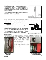
Page 16: ...onduit entry locations are required in areas other than the removable plates cover the electrical assemblies to prevent metal filings from becoming lodged in areas which may cause a reduction in the high voltage clearances or a short circuit After the work is completed thoroughly clean the area and inspect the unit for foreign material Fig 7 Securely Anchor the Controller Ground Connections The co...

Page 17: ...line or any sensor used for ground fault protection No connections should be made between outgoing grounding connectors and the neutral e Where the controller or system is dual fed double ended and has ground fault protection special precautions are necessary to accomplish proper grounding and bonding Controller used as service equipment for an ungrounded system or as a main section for a separate...

Page 18: ...rry the motor full load current in accordance with NEC requirements and have an adequate voltage rating Cables should be dressed and terminated as appropriate to the voltage class and cable manufacturer s recommendations Fig 10a Torque Specs for MV Power Connections Main power bus when provided and horizontal ground bus are supplied with links to join shipping sections together These should be ins...

Page 19: ... should not be replaced All debris and tools should be removed from each compartment as cabling is completed Remove part number identification or any label on the splice bus before installation Tighten and torque the bolts for all bus splice connections and other bus if loosened during installation of the bus splice Fig 12 Main Bus Splice Connections 2000A Consult Factory for 3000A Main Bus Splice...

Page 20: ...ing Wiring Bottom Entry Load cable termination arrangements for certain controllers such as reduced voltage autotransformer and solid state types may differ from those shown in this manual In these cases refer to the drawings furnished with the equipment To access cable termination areas remove fuse barriers as shown in Fig 45 then remove fuses see Power Fuses section After completing the cable te...

Page 21: ... cartridge 1 Position the cartridge on top of the vacuum contactor Fig 15d Fig 15a Double Barrel Fuse Cartridge 2 Slowly slide the cartridge in until the back bus stab engages inside the isolation switch opening slot Fig 15e 3 Lower the front end bus into the two sems bolts then tighten and torque the sems bolts to 10 15 ft lbs Fig 15b Installed Single Barrel Fuse Cartridges Fig 15d Installing Fus...

Page 22: ... completely tested at the factory a final field check should be made that all electrical wiring and bus bar connections are correct and have not become loose in transportation Fig 17 Refer to the MAINTENANCE Section for electrical joint specification All blocks or other temporary braces used for shipment must be removed Fig 16 Data Label on Controller Before closing the enclosure all metal chips s...

Page 23: ...ld be checked Each load should be connected to its intended controller and phase rotation should be corrected prior to startup Fig 18 Wiring Check Shorting jumpers Fig 19 for current transformer secondary windings must be removed once the secondary circuit is completed A circuit transformer must not be operated with its secondary windings open Changes made to circuit diagrams during installation s...

Page 24: ... etc should be checked for function as intended for protection of personnel and equipment The motor load protection relay should be checked to be sure that proper settings have been programmed per the motor load specification sheet and nameplate Fig 21 Check the instruction manual for the specific relay supplied with your equipment for factory default settings and additional protection and program...

Page 25: ...re free from short circuits and grounds The preferred method is to perform a dielectric test at 2 25 times the nominal system voltage plus 2000 volts This should be done phase to ground phase to phase and phase to neutral if applicable with all switches contactors and circuit breakers opened Disconnect any devices which may have limited dielectric strength and that are not intended for this test T...

Page 26: ...e major compart Fig 22 Typical Controller Arrangements ments each with a separate door The uppermost and lower most compartments contain medium voltage controller components while the middle compartment contains low voltage components Other variations of this basic arrangement are possible Main horizontal bus is provided when required to supply power to a line up of controllers The main bus is loc...

Page 27: ...ls are cabled through three metering current transformers plus a ground sensor if supplied to the outgoing load terminals Current transformers furnished are of the window donut or Fig 24a Isolation Switch bar type The isolation switch is mechanically interlocked with the vacuum contactor and the compartment door Details of the interlocking are discussed in Section F The position of the isolation s...

Page 28: ...er phase or shielded cable up to one 2 0 per phase can be accommodated through the window donut type current transformer and terminated at the provided aluminum mechanical lugs behind the vacuum contactor If necessary the current transformer can be easily removed to feed load cables through opening windows by unscrewing the secondary terminal wires and two mounting nuts Fig 27a Load Cable Connecti...

Page 29: ...rmally connected in an open delta arrangement Another option sometimes supplied is a second control power transformer connected in parallel with the first to increase the available KVA capacity Both the control and optional potential transformers are used to supply power to the low voltage circuits of the controller This includes power for the vacuum contactor operating coil and instrumentation Re...

Page 30: ...o the controller compartment At the same time an automatic shutter within the switch closes providing an effective barrier between the controller compartment and the incoming supply The opening of the switch also causes the line side of the power fuses to be grounded Further details on the isolation switch and external operating handle can be found in the Maintenance section Fig 29 Operating Handl...

Page 31: ...dle from being moved in either direction unless the contacts of the vacuum contactor are open Fig 32 Fig 31 Handle Interlock to Door c Vacuum Contactor Interlock The vacuum contactor is mechanically interlocked to prevent it from closing unless the switch handle is in the fully ON or fully OFF position The interlock shown in Fig 32 provides this function If the switch handle is in an intermediate ...

Page 32: ...atic drawings to confirm number of CPIs in the equipment Do not connect any additional load to the isolation switch Fig 33 Control Power Interlock b Test Power Interlock TPI The test power interlock TPI is a scheme provided to allow simulated operation of the controller from a separate control power test source with power removed from the medium voltage circuit During normal controller operation w...

Page 33: ...lays and other control devices The low voltage subpanel is hinged in such a way that it can be swung open Fig 35a if necessary to gain access to the main horizontal bus by removing barriers Fig 35b located directly behind the panel Hazardous Voltage Turn off and lock out all control and primary power before opening this panel Fig 35a Low Voltage Swing out Panel Fig 35a Access to Main Bus Through L...

Page 34: ...his compartment Bus splice links Fig 37 are furnished for joining the main bus and ground bus between shipping sections With the low voltage subpanel swung open and the main bus barrier removed all splice links can be installed from the front of the unit Refer to Installation Section for details Fig 36a Main Bus 1200A 2000A Compartment A copper ground bus located in front of the main bus compartme...

Page 35: ...1200 Hour Mechanical Life 2 500 000 Operations Electrical Life 250 000 Operations Pick Up Voltage AC or DC 85 Hot 70 Cold Drop Out Voltage AC or DC 70 Hot 60 Cold Rated Control Voltage AC 120 V 50 60 Hz Optional Control Voltage DC 125 V Coil Circuit Inrush 5 4A Peak 120Vac 670VA AC 700W DC Coil Circuit Holding 0 12A Average 120Vac 85VA AC 85W DC Auxiliary Contact Arrangement 3 N O 3 N C Auxiliary ...

Page 36: ...ithstand 1 Minute Impulse Voltage Withstand 50 000 RMS 2 3 6 6kV 7 2kV Max 200 2 3kV 350 4 0kV 400 4 6kV 570 6 6kV 2400 A 6 000 A AC 19 kV DC 26kV 60 kV BIL Table 3 Continuous Current Rating Enclosure Type Max Continuous Amperes One High Controller Max Continuous Amperes Lower Controller in a Two High Stacking Arrangement Max Continuous Amperes Upper Controller in a Two High Stacking Arrangement T...

Page 37: ...nous Motors Induction Motors Synchronous Motors Induction Motors Synchronous Motors Induction Motors 0 8 P F 1 0 P F 0 8 P F 1 0 P F 0 8 P F 1 0 P F 360 1500 1750 1500 2500 3000 2500 4000 5000 4000 320 1250 1500 1250 2250 2500 2250 3500 4500 3500 310 1250 1500 1250 2000 2500 2000 3500 4000 3500 280 1000 1250 1000 1750 2250 1750 3000 3500 3000 Motor FLA depends on manufacturer speed and other facto...

Page 38: ...ze the risk of injury or damage there should be no load on the controller or group of controllers when incoming power is first turned on All downstream loads including distribution equipment and other remote devices should be turned off The isolation switch ahead of each controller should be in the off position The equipment should be energized in sequence by starting at the source end of the syst...

Page 39: ...wer before servicing Improper maintenance can cause severe injury death and extensive property damage Only qualified and authorized persons are to install operate or service the equipment This equipment utilizes both low and high voltage for operation Verify that all test equipment is suitable for the voltage being checked NOTE Refer to the SAFETY section of this manual for important information A...

Page 40: ...or any signs of rusted or corroded parts Check for free movement of all moving parts and mechanisms Lubricate if necessary with Toshiba B9 grease Grease is conductive Do not apply grease to electrical insulation Electrical Joints Examine all visible terminals and joints for signs of overheating Fig 42 An overheated connection will appear discolored Be suspicious of any conducting joint which has a...

Page 41: ...reign material Fig 44a Checking Power Fuse wipe clean and lubricate with a light coat of Toshiba B9 grease Clamping Bolt Torque making sure that no grease gets on the insulated fuse housing Check the fuse barriers for cleanliness and proper positioning as shown in Fig 45 There are three vertical barriers two located between adjacent fuses and a third between the right hand fuse and the operator me...

Page 42: ...e line terminal shutter opens and closes properly Lubricate the moving parts of the handle mechanism and if necessary apply a light coat of Toshiba B9 grease to the inside contact surfaces of the switch blades Contact the equipment supplier or the factory to obtain B9 grease if required Grease is conductive Do not allow grease to contact the switch housing or the insulated shutter Fig 47 Checking ...

Page 43: ...n lock nut securing yoke on handle end of connecting rod Remove pin which attaches yoke to handle drive lever Turn yoke in required direction to achieve adjustment defined in step 2 Attach yoke and pin to drive lever and tighten yoke lock nut Fig 48 Switch Mechanism and Interlock Adjustment 4 Check the position of the handle interlock with the vacuum contactor in the OFF position The tab extending...

Page 44: ...r interlock should close approximately 10 before the handle reaches the full ON position As the handle is moved from ON to OFF the CPI switch should open by the time the handle has moved approximately 10 or one inch Fig 49 Refer to the GENERAL DESCRIPTION section for the location of the handle mechanical interlocks and the CPI electrical interlock Fig 49 Interlock Sequence Check Control Power Pote...

Page 45: ...ires major reconditioning or complete replacement of the controller In this event contact the nearest Toshiba representative Isolation Switch The external operating handle must be capable of opening the switch If the handle fails to open the switch or if visual inspection after opening indicates deterioration beyond normal wear and tear such as overheating or pitting of blades insulation breakage ...

Page 46: ......

Page 47: ......

Page 48: ...Motors and Drives Division Power Apparatus Components 13131 West Little York Road Houston TX 77041 Tel 713 466 0277 US 800 231 1412 CAN 800 872 2192 www toshiba com tic Printed in USA ...

Reviews: