Basic Installation and Operation Guide
JK 400 Series Fixed Controllers
TOSHIBA
30
Power Fuses
The power fuses supplied in Toshiba JK 400 ampere controllers are
of the bolt-in or clamp-in type, therefore overheating due to loss of
fuse clip pressure is not a problem. The tightness of the fuse
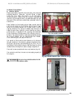
clamping bolts (Fig.
44a) should, however, be periodically checked
and maintained within a range of 4-6 ft-lbs.
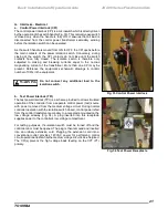
Check the condition of the back stab terminals on the cartridge for
any signs of damage or discoloration
(Fig. 44b)
. Check the power
fuses for any signs of discoloration. A fuse barrel which appears
darker than others indicates overheating. Possible causes of fuse
overheating, other than load problems, are misapplication (fuse
current rating too small), loose fuse connections, or a damaged
fuse.
If there is any excessive build-up of dirt or other foreign material,
Fig. 44a Checking Power Fuse
wipe clean and lubricate with a light coat of Toshiba B9 grease,
Clamping Bolt Torque
making sure that no grease gets on the insulated fuse housing.
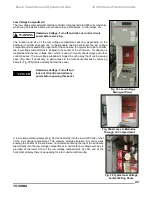
Check the fuse barriers for cleanliness and proper positioning, as
shown in Fig.
45. There are three vertical barriers, two located
between adjacent fuses and a third between the right hand fuse and
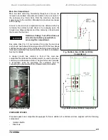
the operator mechanism. A fourth angle-shaped barrier is
positioned in front of the isolation switch
(Fig. 46)
.
Vacuum Contactor
Maintenance instructions for the H
CV-
5HA/7HA
vacuum contactor
are provided in a separate publication, number
V
F010H
08A
/VF00W104
. Contact the equipment supplier or the
factory if this publication is needed and was not provided with the
equipment.
Radiation Exposure Hazard. X-Radiation
may cause illness or injury. Stay at least Fig. 44b Checking Stab on Power
1 meter (3.3 feet) away from the contactor
Fuse Cartridge
during high-potential tests.
Fig. 46 Angled Barrier In
Front of The Isolation Switch
Fig. 45 Fuse Barrier Placement
CAUTION

