6F8A0917
- 155 -
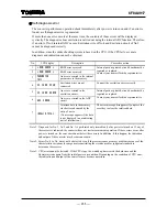
Self-diagnosis error
The converter performs an operation check immediately after power is turned on and if an error is
found, a self-diagnosis error is generated.
If more than one error occurs at the same time, the contents of those errors will be displayed
cyclically. The diagnosis about excitation is carried out using the internal ADC function. Therefore,
if an error of No.6 internal ADC occurs, Excitation wire of No.4 and Excitation circuit of No.5
cannot be diagnosed correctly.
In addition, since the entire checking system is based on the CPU, if the CPU fails, accurate
diagnosis and indication cannot be obtained.
No. LCD
display
Description
Corrective
action
1
* ROM ERROR *
ROM error occurred
2
* RAM ERROR *
RAM error occurred
3
PARAMETER
FAIL
An error occurred in the internal
parameters in the memory
Internal parts or printed-circuit board must be
repaired or replaced.
Contact your nearest Toshiba representative.
4
EX. CURR. OPEN
Excitation wires are not
connected.
Connect the excitation wires correctly.
5
EX. CURR. ERROR
An error occurred in the
excitation circuit.
6
ADC. ERROR
An error occurred in the ADC
circuit
Internal parts or printed-circuit board must be
repaired or replaced.
Contact your nearest Toshiba representative.
7
INVALID TOTAL
Totalized data in the memory
was destroyed caused by the
entry of noise.
(No message appears if the data
is not displayed in an indicating
unit of totalization.)
The error message disappears if you press the
reset key to clear the totalized data.
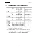
Note 1: Diagnosis for No. 1, No.2 and No. 3 is performed only immediately after power is turned on. If any of
these errors is indicated, the converter does not start measurement operation. If these errors occur after
power is turned on, the converter cannot detect these errors. In addition, if this happen, the indication
and output of the converter may become uncertain.
Note 2: Errors No. 4 to No. 6 may not be detected even if those errors cause accuracy problems because of the
characteristic variations in components constituting the circuits used for judgment standard to
determine these errors.
Note 3: CPU error cannot be detected. If the CPU stops, the watchdog timer resets the hardware and the
flowmeter starts again from the initial power-on condition. Depending on the condition of CPU error,
the indication and output of the converter may become uncertain.


