31
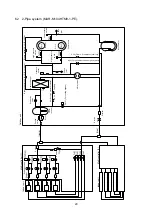
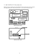
L1 L2 L3 N
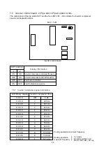
LED 1~8
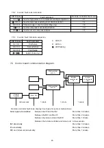
Interface control board
M/C (1) M/C (2)
MCC-1252
MCC-1211
Connectors
R S T
52C3
U V W
51C3
Power supply
1 2 3
Fuse 20Ax3
Power
Transistor
1 2 3
Interface control board
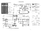
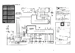
Electrical parts location
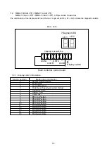
Malfunction judgement is performed using the self-diagnostic function of the outdoor unit. The
combination of the display switch and the 8 LED's (LED 1 ~ LED 8) indicate the diagnostic details.
7.1
MAR-C104M8-1-PE, MAR-M104HTM8-1-PE, 2-Pipe Outdoor Unit.
Display switch
➤
Electrolytic
Capacitors
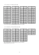
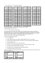
7.1.1 Display switch information.
MCC-1251
Inverter control
board
MCC-1211
J2
➤
Switch position
Malfunction information
0
System Communication
1
Status of Compressors
2
System Status
3
Fault Diagnostics (Outdoor Units)
4
M/C 1 Units A & B Indoor Capacity Codes
5
M/C 1 Units C & D Indoor Capacity Codes
6
M/C 2 Units A & B Indoor Capacity Codes
7
M/C 2 Units C & D Indoor Capacity Codes
8
Fault Diagnostics (Multi Controller)
9
Circuit Test
10 ~ 15
Not used
7. SELF DIAGNOSTIC DISPLAY INFORMATION
Summary of Contents for MAR-C104M8-1-PE
Page 2: ......
Page 22: ......
Page 58: ...61 13 EXPLODED VIEWS AND SERVICE PARTS LISTS 13 1 Outdoor Unit MAR C104M8 1 PE ...
Page 60: ...63 13 3 Outdoor Units MAR M104HTM8 1 PE MAR F104HTM8 1 PE ...
Page 63: ...66 13 6 Outdoor unit electrical parts assembly MAR C104M8 1 PE ...
Page 65: ...68 MAR M104HTM8 1 PE MAR F104HTM8 1 PE ...
Page 72: ......


