45
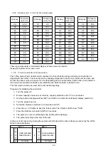
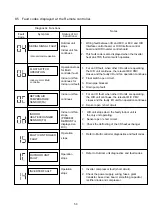
7.5.2
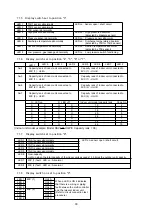
Inverter fault code indication.
LED Display
Fault indicated
LED Display
Fault indicated
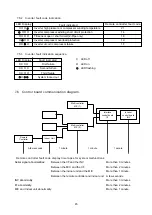
7.6
Control board communication diagram.
Indoor Unit
Remote
Controller
Multi controller
M/C (1)
Multi controller
M/C (2)
Interface
control board
I/F
Inverter
control board
INV
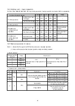
Remote controller fault code display time lapse for system malfunctions.
Serial signal abnormalities:
Between the I/F and the INV
More than 3 minutes.
Between the M/C and the I/F
More than 2 minutes.
Between the indoor unit and the M/C
More than 1 minute.
Between the remote controller and indoor unit
A few seconds.
INV abnormality:
More than 3 minutes.
I/F abnormality:
More than 2 minutes.
M/C and Indoor unit abnormality:
More than 1 minute.
1 minute
1 minute
1 minute
A few seconds
Remote controller fault code
21
14
18
1d
1F
Inverter high pressure or compressor winding temperature
Inverter compressor winding short circuit protection
TE sensor open / short circuit (2-Pipe only)
Inverter compressor overload protection
Inverter circuit / compressor failure
First failure
Second failure
Third failure
System locked out
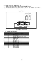
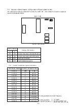
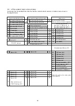
7.5.3
Inverter fault indication sequence.
X
LED off
O LED on
LED flashing
X
X X X O
X X O X
X X O O
O
X
X X
O O O
O O O
O O O O
O O O
O O O
X
X
X
X
Summary of Contents for MAR-C104M8-1-PE
Page 2: ......
Page 22: ......
Page 58: ...61 13 EXPLODED VIEWS AND SERVICE PARTS LISTS 13 1 Outdoor Unit MAR C104M8 1 PE ...
Page 60: ...63 13 3 Outdoor Units MAR M104HTM8 1 PE MAR F104HTM8 1 PE ...
Page 63: ...66 13 6 Outdoor unit electrical parts assembly MAR C104M8 1 PE ...
Page 65: ...68 MAR M104HTM8 1 PE MAR F104HTM8 1 PE ...
Page 72: ......


