background image

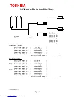
8. Calculating The Additional Gas Charge

Main Pipes
0.19 kg/m

Sub Pipes
0.125 kg/m

Branch Pipes
RAV-103 ; 0.030 kg/m  
RAV-133 ; 0.030 kg/m
RAV-162 ; 0.030 kg/m
RAV-202 ; 0.030 kg/m 

RAV-262 ; 0.045 kg/m
RAV-362 ; 0.045 kg/m
RAV-462 ; 0.045 kg/m

Single Multi Controller

Main pipe run  (minus 3m.)

x

 0.190 kg/m

=

Branch pipe A (minus 2m.)

x

see above kg/m

=

Branch pipe B (minus 2m.)

x

see above kg/m

=

Branch pipe C (minus 2m.)

x

see above kg/m

=

Branch pipe D (minus 2m.)

x

see above kg/m

=

Total Additional Gas Charge  = _________________kg

Two Multi Controllers

Main pipe run (minus 2m.)

x

0.190 kg/m

=

Total sub pipe (minus 2m.)

x

0.125 kg/m

=

M/C1 Branch pipe A (minus 2m.)

x

see above kg/m

=

Branch pipe B (minus 2m.)

x

see above kg/m

=

Branch pipe C (minus 2m.)

x

see above kg/m

=

Branch pipe D (minus 2m.)

x

see above kg/m

=

M/C2 Branch pipe A (minus 2m.)

x

see above kg/m

=

Branch pipe B (minus 2m.)

x

see above kg/m

=

Branch pipe C (minus 2m.)

x

see above kg/m

=

Branch pipe D (minus 2m.)

x

see above kg/m

=

Total Additional Gas Charge  = _________________kg


TOSHIBA

AUGUST 1997

Page  19

Summary of Contents for MAR - M101HTM8 - E

Page 1: ...SERVICE MANUAL AIR CONDITIONER HEAT PUMP MULTI SPLIT 2 PIPE Outdoor Units MAR M81HTM8 E MAR M101HTM8 E Multi Controllers RBM Y1032E E RBM Y1042E E TOSHIBA AUGUST 1997 Page 1 ...

Page 2: ...it Multi Controller 5 Refrigeration Circuit Outdoor Unit Multi Controller 6 Display Information and Fault Codes 7 Circuit Test Procedure 8 Calculation for Additional Gas Charge Note The two pipe Super Multi systems are heat pump units and can provide heating or cooling where both modes are required simultaneously heating mode takes priority TOSHIBA AUGUST 1997 Page 2 ...

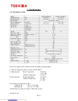
Page 3: ...vel SPL 315 308 kg Weight 824 Depth mm 1 290 Width mm 1 490 Height mm Dimensions 60 Amps Start Current 15 7 15 0 12 3 11 7 C H Amps Running Current 10 1 10 1 8 0 7 7 C H kW Power Consumption 3ph 380 415v 50Hz Power Supply 25 0 31 5 20 0 25 0 kW Heating Capacity 25 0 28 0 20 0 22 4 kW Cooling Capacity MAR M101HTM8 E MAR M81HTM8 E Model Note The capacity value in brackets is the maximum operating ca...

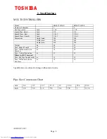
Page 4: ...520 450 Depth mm 590 590 Width mm 260 260 Height mm Dimensions 3 8 x 4 3 8 x 3 Inch Branch Pipes Liquid 3 4 x 4 3 4 x 3 Inch Branch Pipes Gas 5 8 5 8 Inch Liquid Pipe Inlet 1 1 8 1 1 8 Inch Gas Pipe Inlet 4 3 Number of Branches RBM Y1042E E RBM Y1032E E Model Specifications are subject to change without prior notice Pipe Size Conversion Chart 1 1 8 1 7 8 3 4 5 8 1 2 3 8 1 4 inch 28 6 25 4 22 4 19 ...

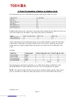
Page 5: ... multi controller is required if more single indoor units are needed then two multi controllers must be used When connecting a twin indoor arrangement to one multi controller branch the capacity code will be the sum of both indoor unit codes Example 24 Total 10 5 Twin RAV202KH W 5 5 Single RAV202KH W 6 3 Twin RAV133TUH 3 3 Single RAV133TUH Total Capacity Code Indoor Capacity Code Arrangement Model...

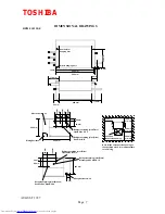
Page 6: ...CONSTRUCTION VIEWS MAR M81HTM8E E MAR M101FHTM8E E 790 mm 824 mm 375 mm 750 mm 120 mm 65 mm 650 mm 1100 mm 1290 mm 610 mm 1182 mm 98 mm 90 mm 130 mm 160 mm 135 mm L G TOSHIBA AUGUST 1997 Page 6 ...

Page 7: ...ing joint Flare Gas Side Ø 19 60 mm Wiring Entrance Ø 36 80 mm 100 mm 125 mm Refrigerant piping joint Flare Liquid Side Ø 15 9 Refrigerant piping joint Brazed Suction Gas Side Ø 28 6 Refrigerant piping joint Flare Discharge Gas Side Ø 19 100 mm or more 500 mm or more 500 mm or more 500 mm or more 450 x 450 Inspection opening Note Make an inspection opening at the specified place It is indispensabl...

Page 8: ... joint Flare Gas Side Ø 19 60 mm Wiring Entrance Ø 36 80 mm 190 mm 125 mm Refrigerant piping joint Flare Liquid Side Ø 15 9 Refrigerant piping joint Brazed Suction Gas Side Ø 28 6 Refrigerant piping joint Flare Discharge Gas Side Ø 19 100 mm or more 500 mm or more 500 mm or more 500 mm or more 450 x 450 Inspection opening Note Make an inspection opening at the specified place It is indispensable f...

Page 9: ... POWER SUPPLY 50Hz 3ℜ 380 415 v Display Switch Display LED x 8 Diode Clipper Diode Clipper CD2 CD2 Reactor Rectifier Electric Starter Contactor 52C2 Contactor 52C1 Capacitor 1λF x 3 Fuses 20A x 3 Crankcase Heater Inverter HP Sw 63H1 Inverter Klixon 49C1 DOL Klixon 49C2 DOL HP Sw 63H2 Contactor 52C3 Return Lock Surge Absorber Surge Absorber Low Pressure Switch 63L R C 1 R C 2 Tr1 Tr2 Thermal Fuse T...

Page 10: ...PMVC PMVD Float Switch PJ 10 PJ 6 PJ 7 PJ 8 PJ 9 PJ 1 PJ 2 PJ 3 PJ 4 PJ 5 PJ 16 PJ 14 PJ 13 PJ 12 Multi Controller P C Board MCC 1210 Capacity Code Swiches Branch A Branch B Branch C Branch D Display Switch The colours used in this diagram are not representative of those on the product they are intended to indicate the status of each wire 240v ac Live Wiring Neutral Wiring Serial Wiring Earth Wiri...

Page 11: ...y Valve 32 8 0ºC 10 25ºC 3 6 50ºC kΩ ThS ThE 50 25ºC 17 9 50ºC 3 35 100ºC kΩ ThD1 ThD2 Sensor Break on Drop Trip 3 5 Reset 20 P S I G L P Switch Make on Rise Trip 425 Reset 340 P S I G H P Switch DOL Break on Rise Trip 425 Reset 340 P S I G H P Switch Inv Trip 115ºC 5ºC Thermal Cut out 6 No Poles 1 12 1 44 Current A 150 Consumption W 220 240 single phase 50Hz Neutral Power Supply Single Phase Indu...

Page 12: ...ary v ac Transformer 1 Amps Heater Fuse Trips at 119 ºC Thermal Fuse 65 50 W Sump Heater 240vac Break on Rise Float Switch 32 8 0ºC 10 25ºC 3 6 50ºC kΩ ThA B C D X Sensor RBM Y1042E E RBM Y1032E E Model Number TOSHIBA AUGUST 1997 Page 12 STRAINER EXPANSION VALVE PMV D CHECK VALVE EXPANSION VALVE STRAINER PMV C CHECK VALVE EXPANSION VALVE PMV B STRAINER CHECK VALVE STRAINER EXPANSION VALVE PMV A CH...

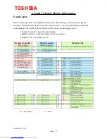
Page 13: ...ensor LED4 ThS Sensor Fault LED3 ThD2 Sensor Fault LED2 ThD1 Sensor Fault LED1 è Refer to O D 1C è Refer to O D 1C Display Switch set to 3 if lit M C2 Sensor Fault LED8 M C1 Sensor Fault LED7 ID Codes set to Zero M C Settings too High LED6 ç ID Codes too High 89 è Preheat Defrost Flash M C Water Level ç M C Water Level Ob ì Refer to Multi Con 15 Th X Sensor Fault LED5 ç Th X Sensor Fault 84 Th D S...

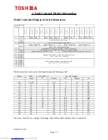
Page 14: ...x Code 13 ThC Sensor Data Hex Code 14 ThD Sensor Data Hex Code 15 ThX Sensor Data Hex Code Outdoor Unit Switch position Information 0 System Communication 1 Status of Compressors 2 System Status Mode Defrost PMV 3 Fault Diagnostics Outdoor Unit 4 M C1 Branches A B Indoor Capacity Codes 5 M C1 Branches C D Indoor Capacity Codes 6 M C2 Branches A B Indoor Capacity Codes 7 M C2 Branches C D Indoor Ca...

Page 15: ... For Details of Fault Codes see Page 13 Fault Codes 1 To Outdoor From C Branch To C Branch To D Branch From D Branch From Outdoor From A Branch To A Branch To B Branch From B Branch Serial 0 _ _ _ _ _ _ _ _ _ _ _ _ _ _ _ _ _ _ _ _ _ _ _ _ _ _ _ _ _ _ _ _ _ _ _ _ _ _ _ _ _ _ _ _ _ _ _ _ LD 2 LD 1 Indicates Switch Pos The Hexadecimal codes can be interpreted using the following chart 90 1F 41 OF 240...

Page 16: ...ller 2 LED 4 Lit Receiving serial signal from multi controller 2 LED 3 Lit Sending serial signal to multi controller 1 LED 2 Lit Receiving serial signal from multi controller 1 LED 1 b Display switch set to position 1 shows status of both compressors O O O O 122 Hz SF X O O O 111 Hz SE O X O O 103 Hz SD X X O O 92 Hz SC O O X O 84 Hz SB X O X O 76 Hz SA O X X O 69 Hz S9 X X X O 61 Hz S8 O O O X 53...

Page 17: ...Pos 7 Capacity code of unit on M C 2 branch B Capacity code of unit on M C 2 branch A Pos 6 Capacity code of unit on M C 1 branch D Capacity code of unit on M C 1 branch C Pos 5 Capacity code of unit on M C 1 branch B Capacity code of unit on M C 1 branch A Pos 4 LED 8 LED 7 LED 6 LED 5 LED4 LED 3 LED 2 LED 1 f Display switch set to position 8 identifies a fault condition in the multi controller D...

Page 18: ...ing stage Procedure for initialising the circuit test 1 Turn the power off and disconnect any T2s optional fitted 2 Put the outdoor display switch to 9 and multi controller s display switch to 6 3 Turn the power back on 4 Set all the remote controllers to cool mode and 29ºC 5 Press the on off button to start the indoor units fans will run 6 Go to outdoor unit press switch J2 above 8 x LEDs for 3 s...

Page 19: ...above kg m Branch pipe D minus 2m x see above kg m Total Additional Gas Charge _________________kg Two Multi Controllers Main pipe run minus 2m x 0 190 kg m Total sub pipe minus 2m x 0 125 kg m M C1 Branch pipe A minus 2m x see above kg m Branch pipe B minus 2m x see above kg m Branch pipe C minus 2m x see above kg m Branch pipe D minus 2m x see above kg m M C2 Branch pipe A minus 2m x see above k...

Page 20: ...SERVICE MANUAL AIR CONDITIONER HEAT PUMP MULTI SPLIT 2 PIPE Outdoor Units MAR M81HTM8 E MAR M101HTM8 E Multi Controllers RBM Y1032E E RBM Y1042E E TOSHIBA AUGUST 1997 Page 1 ...

Page 21: ...it Multi Controller 5 Refrigeration Circuit Outdoor Unit Multi Controller 6 Display Information and Fault Codes 7 Circuit Test Procedure 8 Calculation for Additional Gas Charge Note The two pipe Super Multi systems are heat pump units and can provide heating or cooling where both modes are required simultaneously heating mode takes priority TOSHIBA AUGUST 1997 Page 2 ...

Page 22: ...vel SPL 315 308 kg Weight 824 Depth mm 1 290 Width mm 1 490 Height mm Dimensions 60 Amps Start Current 15 7 15 0 12 3 11 7 C H Amps Running Current 10 1 10 1 8 0 7 7 C H kW Power Consumption 3ph 380 415v 50Hz Power Supply 25 0 31 5 20 0 25 0 kW Heating Capacity 25 0 28 0 20 0 22 4 kW Cooling Capacity MAR M101HTM8 E MAR M81HTM8 E Model Note The capacity value in brackets is the maximum operating ca...

Page 23: ...520 450 Depth mm 590 590 Width mm 260 260 Height mm Dimensions 3 8 x 4 3 8 x 3 Inch Branch Pipes Liquid 3 4 x 4 3 4 x 3 Inch Branch Pipes Gas 5 8 5 8 Inch Liquid Pipe Inlet 1 1 8 1 1 8 Inch Gas Pipe Inlet 4 3 Number of Branches RBM Y1042E E RBM Y1032E E Model Specifications are subject to change without prior notice Pipe Size Conversion Chart 1 1 8 1 7 8 3 4 5 8 1 2 3 8 1 4 inch 28 6 25 4 22 4 19 ...

Page 24: ... multi controller is required if more single indoor units are needed then two multi controllers must be used When connecting a twin indoor arrangement to one multi controller branch the capacity code will be the sum of both indoor unit codes Example 24 Total 10 5 Twin RAV202KH W 5 5 Single RAV202KH W 6 3 Twin RAV133TUH 3 3 Single RAV133TUH Total Capacity Code Indoor Capacity Code Arrangement Model...

Page 25: ...CONSTRUCTION VIEWS MAR M81HTM8E E MAR M101FHTM8E E 790 mm 824 mm 375 mm 750 mm 120 mm 65 mm 650 mm 1100 mm 1290 mm 610 mm 1182 mm 98 mm 90 mm 130 mm 160 mm 135 mm L G TOSHIBA AUGUST 1997 Page 6 ...

Page 26: ...ing joint Flare Gas Side Ø 19 60 mm Wiring Entrance Ø 36 80 mm 100 mm 125 mm Refrigerant piping joint Flare Liquid Side Ø 15 9 Refrigerant piping joint Brazed Suction Gas Side Ø 28 6 Refrigerant piping joint Flare Discharge Gas Side Ø 19 100 mm or more 500 mm or more 500 mm or more 500 mm or more 450 x 450 Inspection opening Note Make an inspection opening at the specified place It is indispensabl...

Page 27: ... joint Flare Gas Side Ø 19 60 mm Wiring Entrance Ø 36 80 mm 190 mm 125 mm Refrigerant piping joint Flare Liquid Side Ø 15 9 Refrigerant piping joint Brazed Suction Gas Side Ø 28 6 Refrigerant piping joint Flare Discharge Gas Side Ø 19 100 mm or more 500 mm or more 500 mm or more 500 mm or more 450 x 450 Inspection opening Note Make an inspection opening at the specified place It is indispensable f...

Page 28: ... POWER SUPPLY 50Hz 3ℜ 380 415 v Display Switch Display LED x 8 Diode Clipper Diode Clipper CD2 CD2 Reactor Rectifier Electric Starter Contactor 52C2 Contactor 52C1 Capacitor 1λF x 3 Fuses 20A x 3 Crankcase Heater Inverter HP Sw 63H1 Inverter Klixon 49C1 DOL Klixon 49C2 DOL HP Sw 63H2 Contactor 52C3 Return Lock Surge Absorber Surge Absorber Low Pressure Switch 63L R C 1 R C 2 Tr1 Tr2 Thermal Fuse T...

Page 29: ...PMVC PMVD Float Switch PJ 10 PJ 6 PJ 7 PJ 8 PJ 9 PJ 1 PJ 2 PJ 3 PJ 4 PJ 5 PJ 16 PJ 14 PJ 13 PJ 12 Multi Controller P C Board MCC 1210 Capacity Code Swiches Branch A Branch B Branch C Branch D Display Switch The colours used in this diagram are not representative of those on the product they are intended to indicate the status of each wire 240v ac Live Wiring Neutral Wiring Serial Wiring Earth Wiri...

Page 30: ...y Valve 32 8 0ºC 10 25ºC 3 6 50ºC kΩ ThS ThE 50 25ºC 17 9 50ºC 3 35 100ºC kΩ ThD1 ThD2 Sensor Break on Drop Trip 3 5 Reset 20 P S I G L P Switch Make on Rise Trip 425 Reset 340 P S I G H P Switch DOL Break on Rise Trip 425 Reset 340 P S I G H P Switch Inv Trip 115ºC 5ºC Thermal Cut out 6 No Poles 1 12 1 44 Current A 150 Consumption W 220 240 single phase 50Hz Neutral Power Supply Single Phase Indu...

Page 31: ...ary v ac Transformer 1 Amps Heater Fuse Trips at 119 ºC Thermal Fuse 65 50 W Sump Heater 240vac Break on Rise Float Switch 32 8 0ºC 10 25ºC 3 6 50ºC kΩ ThA B C D X Sensor RBM Y1042E E RBM Y1032E E Model Number TOSHIBA AUGUST 1997 Page 12 STRAINER EXPANSION VALVE PMV D CHECK VALVE EXPANSION VALVE STRAINER PMV C CHECK VALVE EXPANSION VALVE PMV B STRAINER CHECK VALVE STRAINER EXPANSION VALVE PMV A CH...

Page 32: ...ensor LED4 ThS Sensor Fault LED3 ThD2 Sensor Fault LED2 ThD1 Sensor Fault LED1 è Refer to O D 1C è Refer to O D 1C Display Switch set to 3 if lit M C2 Sensor Fault LED8 M C1 Sensor Fault LED7 ID Codes set to Zero M C Settings too High LED6 ç ID Codes too High 89 è Preheat Defrost Flash M C Water Level ç M C Water Level Ob ì Refer to Multi Con 15 Th X Sensor Fault LED5 ç Th X Sensor Fault 84 Th D S...

Page 33: ...x Code 13 ThC Sensor Data Hex Code 14 ThD Sensor Data Hex Code 15 ThX Sensor Data Hex Code Outdoor Unit Switch position Information 0 System Communication 1 Status of Compressors 2 System Status Mode Defrost PMV 3 Fault Diagnostics Outdoor Unit 4 M C1 Branches A B Indoor Capacity Codes 5 M C1 Branches C D Indoor Capacity Codes 6 M C2 Branches A B Indoor Capacity Codes 7 M C2 Branches C D Indoor Ca...

Page 34: ... For Details of Fault Codes see Page 13 Fault Codes 1 To Outdoor From C Branch To C Branch To D Branch From D Branch From Outdoor From A Branch To A Branch To B Branch From B Branch Serial 0 _ _ _ _ _ _ _ _ _ _ _ _ _ _ _ _ _ _ _ _ _ _ _ _ _ _ _ _ _ _ _ _ _ _ _ _ _ _ _ _ _ _ _ _ _ _ _ _ LD 2 LD 1 Indicates Switch Pos The Hexadecimal codes can be interpreted using the following chart 90 1F 41 OF 240...

Page 35: ...ller 2 LED 4 Lit Receiving serial signal from multi controller 2 LED 3 Lit Sending serial signal to multi controller 1 LED 2 Lit Receiving serial signal from multi controller 1 LED 1 b Display switch set to position 1 shows status of both compressors O O O O 122 Hz SF X O O O 111 Hz SE O X O O 103 Hz SD X X O O 92 Hz SC O O X O 84 Hz SB X O X O 76 Hz SA O X X O 69 Hz S9 X X X O 61 Hz S8 O O O X 53...

Page 36: ...Pos 7 Capacity code of unit on M C 2 branch B Capacity code of unit on M C 2 branch A Pos 6 Capacity code of unit on M C 1 branch D Capacity code of unit on M C 1 branch C Pos 5 Capacity code of unit on M C 1 branch B Capacity code of unit on M C 1 branch A Pos 4 LED 8 LED 7 LED 6 LED 5 LED4 LED 3 LED 2 LED 1 f Display switch set to position 8 identifies a fault condition in the multi controller D...

Page 37: ...ing stage Procedure for initialising the circuit test 1 Turn the power off and disconnect any T2s optional fitted 2 Put the outdoor display switch to 9 and multi controller s display switch to 6 3 Turn the power back on 4 Set all the remote controllers to cool mode and 29ºC 5 Press the on off button to start the indoor units fans will run 6 Go to outdoor unit press switch J2 above 8 x LEDs for 3 s...

Page 38: ...above kg m Branch pipe D minus 2m x see above kg m Total Additional Gas Charge _________________kg Two Multi Controllers Main pipe run minus 2m x 0 190 kg m Total sub pipe minus 2m x 0 125 kg m M C1 Branch pipe A minus 2m x see above kg m Branch pipe B minus 2m x see above kg m Branch pipe C minus 2m x see above kg m Branch pipe D minus 2m x see above kg m M C2 Branch pipe A minus 2m x see above k...

Page 39: ...SERVICE MANUAL AIR CONDITIONER HEAT PUMP MULTI SPLIT 2 PIPE Outdoor Units MAR M81HTM8 E MAR M101HTM8 E Multi Controllers RBM Y1032E E RBM Y1042E E TOSHIBA AUGUST 1997 Page 1 ...

Page 40: ...it Multi Controller 5 Refrigeration Circuit Outdoor Unit Multi Controller 6 Display Information and Fault Codes 7 Circuit Test Procedure 8 Calculation for Additional Gas Charge Note The two pipe Super Multi systems are heat pump units and can provide heating or cooling where both modes are required simultaneously heating mode takes priority TOSHIBA AUGUST 1997 Page 2 ...

Page 41: ...vel SPL 315 308 kg Weight 824 Depth mm 1 290 Width mm 1 490 Height mm Dimensions 60 Amps Start Current 15 7 15 0 12 3 11 7 C H Amps Running Current 10 1 10 1 8 0 7 7 C H kW Power Consumption 3ph 380 415v 50Hz Power Supply 25 0 31 5 20 0 25 0 kW Heating Capacity 25 0 28 0 20 0 22 4 kW Cooling Capacity MAR M101HTM8 E MAR M81HTM8 E Model Note The capacity value in brackets is the maximum operating ca...

Page 42: ...520 450 Depth mm 590 590 Width mm 260 260 Height mm Dimensions 3 8 x 4 3 8 x 3 Inch Branch Pipes Liquid 3 4 x 4 3 4 x 3 Inch Branch Pipes Gas 5 8 5 8 Inch Liquid Pipe Inlet 1 1 8 1 1 8 Inch Gas Pipe Inlet 4 3 Number of Branches RBM Y1042E E RBM Y1032E E Model Specifications are subject to change without prior notice Pipe Size Conversion Chart 1 1 8 1 7 8 3 4 5 8 1 2 3 8 1 4 inch 28 6 25 4 22 4 19 ...

Page 43: ... multi controller is required if more single indoor units are needed then two multi controllers must be used When connecting a twin indoor arrangement to one multi controller branch the capacity code will be the sum of both indoor unit codes Example 24 Total 10 5 Twin RAV202KH W 5 5 Single RAV202KH W 6 3 Twin RAV133TUH 3 3 Single RAV133TUH Total Capacity Code Indoor Capacity Code Arrangement Model...

Page 44: ...CONSTRUCTION VIEWS MAR M81HTM8E E MAR M101FHTM8E E 790 mm 824 mm 375 mm 750 mm 120 mm 65 mm 650 mm 1100 mm 1290 mm 610 mm 1182 mm 98 mm 90 mm 130 mm 160 mm 135 mm L G TOSHIBA AUGUST 1997 Page 6 ...

Page 45: ...ing joint Flare Gas Side Ø 19 60 mm Wiring Entrance Ø 36 80 mm 100 mm 125 mm Refrigerant piping joint Flare Liquid Side Ø 15 9 Refrigerant piping joint Brazed Suction Gas Side Ø 28 6 Refrigerant piping joint Flare Discharge Gas Side Ø 19 100 mm or more 500 mm or more 500 mm or more 500 mm or more 450 x 450 Inspection opening Note Make an inspection opening at the specified place It is indispensabl...

Page 46: ... joint Flare Gas Side Ø 19 60 mm Wiring Entrance Ø 36 80 mm 190 mm 125 mm Refrigerant piping joint Flare Liquid Side Ø 15 9 Refrigerant piping joint Brazed Suction Gas Side Ø 28 6 Refrigerant piping joint Flare Discharge Gas Side Ø 19 100 mm or more 500 mm or more 500 mm or more 500 mm or more 450 x 450 Inspection opening Note Make an inspection opening at the specified place It is indispensable f...

Page 47: ... POWER SUPPLY 50Hz 3ℜ 380 415 v Display Switch Display LED x 8 Diode Clipper Diode Clipper CD2 CD2 Reactor Rectifier Electric Starter Contactor 52C2 Contactor 52C1 Capacitor 1λF x 3 Fuses 20A x 3 Crankcase Heater Inverter HP Sw 63H1 Inverter Klixon 49C1 DOL Klixon 49C2 DOL HP Sw 63H2 Contactor 52C3 Return Lock Surge Absorber Surge Absorber Low Pressure Switch 63L R C 1 R C 2 Tr1 Tr2 Thermal Fuse T...

Page 48: ...PMVC PMVD Float Switch PJ 10 PJ 6 PJ 7 PJ 8 PJ 9 PJ 1 PJ 2 PJ 3 PJ 4 PJ 5 PJ 16 PJ 14 PJ 13 PJ 12 Multi Controller P C Board MCC 1210 Capacity Code Swiches Branch A Branch B Branch C Branch D Display Switch The colours used in this diagram are not representative of those on the product they are intended to indicate the status of each wire 240v ac Live Wiring Neutral Wiring Serial Wiring Earth Wiri...

Page 49: ...y Valve 32 8 0ºC 10 25ºC 3 6 50ºC kΩ ThS ThE 50 25ºC 17 9 50ºC 3 35 100ºC kΩ ThD1 ThD2 Sensor Break on Drop Trip 3 5 Reset 20 P S I G L P Switch Make on Rise Trip 425 Reset 340 P S I G H P Switch DOL Break on Rise Trip 425 Reset 340 P S I G H P Switch Inv Trip 115ºC 5ºC Thermal Cut out 6 No Poles 1 12 1 44 Current A 150 Consumption W 220 240 single phase 50Hz Neutral Power Supply Single Phase Indu...

Page 50: ...ary v ac Transformer 1 Amps Heater Fuse Trips at 119 ºC Thermal Fuse 65 50 W Sump Heater 240vac Break on Rise Float Switch 32 8 0ºC 10 25ºC 3 6 50ºC kΩ ThA B C D X Sensor RBM Y1042E E RBM Y1032E E Model Number TOSHIBA AUGUST 1997 Page 12 STRAINER EXPANSION VALVE PMV D CHECK VALVE EXPANSION VALVE STRAINER PMV C CHECK VALVE EXPANSION VALVE PMV B STRAINER CHECK VALVE STRAINER EXPANSION VALVE PMV A CH...

Page 51: ...ensor LED4 ThS Sensor Fault LED3 ThD2 Sensor Fault LED2 ThD1 Sensor Fault LED1 è Refer to O D 1C è Refer to O D 1C Display Switch set to 3 if lit M C2 Sensor Fault LED8 M C1 Sensor Fault LED7 ID Codes set to Zero M C Settings too High LED6 ç ID Codes too High 89 è Preheat Defrost Flash M C Water Level ç M C Water Level Ob ì Refer to Multi Con 15 Th X Sensor Fault LED5 ç Th X Sensor Fault 84 Th D S...

Page 52: ...x Code 13 ThC Sensor Data Hex Code 14 ThD Sensor Data Hex Code 15 ThX Sensor Data Hex Code Outdoor Unit Switch position Information 0 System Communication 1 Status of Compressors 2 System Status Mode Defrost PMV 3 Fault Diagnostics Outdoor Unit 4 M C1 Branches A B Indoor Capacity Codes 5 M C1 Branches C D Indoor Capacity Codes 6 M C2 Branches A B Indoor Capacity Codes 7 M C2 Branches C D Indoor Ca...

Page 53: ... For Details of Fault Codes see Page 13 Fault Codes 1 To Outdoor From C Branch To C Branch To D Branch From D Branch From Outdoor From A Branch To A Branch To B Branch From B Branch Serial 0 _ _ _ _ _ _ _ _ _ _ _ _ _ _ _ _ _ _ _ _ _ _ _ _ _ _ _ _ _ _ _ _ _ _ _ _ _ _ _ _ _ _ _ _ _ _ _ _ LD 2 LD 1 Indicates Switch Pos The Hexadecimal codes can be interpreted using the following chart 90 1F 41 OF 240...

Page 54: ...ller 2 LED 4 Lit Receiving serial signal from multi controller 2 LED 3 Lit Sending serial signal to multi controller 1 LED 2 Lit Receiving serial signal from multi controller 1 LED 1 b Display switch set to position 1 shows status of both compressors O O O O 122 Hz SF X O O O 111 Hz SE O X O O 103 Hz SD X X O O 92 Hz SC O O X O 84 Hz SB X O X O 76 Hz SA O X X O 69 Hz S9 X X X O 61 Hz S8 O O O X 53...

Page 55: ...Pos 7 Capacity code of unit on M C 2 branch B Capacity code of unit on M C 2 branch A Pos 6 Capacity code of unit on M C 1 branch D Capacity code of unit on M C 1 branch C Pos 5 Capacity code of unit on M C 1 branch B Capacity code of unit on M C 1 branch A Pos 4 LED 8 LED 7 LED 6 LED 5 LED4 LED 3 LED 2 LED 1 f Display switch set to position 8 identifies a fault condition in the multi controller D...

Page 56: ...ing stage Procedure for initialising the circuit test 1 Turn the power off and disconnect any T2s optional fitted 2 Put the outdoor display switch to 9 and multi controller s display switch to 6 3 Turn the power back on 4 Set all the remote controllers to cool mode and 29ºC 5 Press the on off button to start the indoor units fans will run 6 Go to outdoor unit press switch J2 above 8 x LEDs for 3 s...

Page 57: ...above kg m Branch pipe D minus 2m x see above kg m Total Additional Gas Charge _________________kg Two Multi Controllers Main pipe run minus 2m x 0 190 kg m Total sub pipe minus 2m x 0 125 kg m M C1 Branch pipe A minus 2m x see above kg m Branch pipe B minus 2m x see above kg m Branch pipe C minus 2m x see above kg m Branch pipe D minus 2m x see above kg m M C2 Branch pipe A minus 2m x see above k...

Page 58: ...SERVICE MANUAL AIR CONDITIONER HEAT PUMP MULTI SPLIT 2 PIPE Outdoor Units MAR M81HTM8 E MAR M101HTM8 E Multi Controllers RBM Y1032E E RBM Y1042E E TOSHIBA AUGUST 1997 Page 1 ...

Page 59: ...it Multi Controller 5 Refrigeration Circuit Outdoor Unit Multi Controller 6 Display Information and Fault Codes 7 Circuit Test Procedure 8 Calculation for Additional Gas Charge Note The two pipe Super Multi systems are heat pump units and can provide heating or cooling where both modes are required simultaneously heating mode takes priority TOSHIBA AUGUST 1997 Page 2 ...

Page 60: ...vel SPL 315 308 kg Weight 824 Depth mm 1 290 Width mm 1 490 Height mm Dimensions 60 Amps Start Current 15 7 15 0 12 3 11 7 C H Amps Running Current 10 1 10 1 8 0 7 7 C H kW Power Consumption 3ph 380 415v 50Hz Power Supply 25 0 31 5 20 0 25 0 kW Heating Capacity 25 0 28 0 20 0 22 4 kW Cooling Capacity MAR M101HTM8 E MAR M81HTM8 E Model Note The capacity value in brackets is the maximum operating ca...

Page 61: ...520 450 Depth mm 590 590 Width mm 260 260 Height mm Dimensions 3 8 x 4 3 8 x 3 Inch Branch Pipes Liquid 3 4 x 4 3 4 x 3 Inch Branch Pipes Gas 5 8 5 8 Inch Liquid Pipe Inlet 1 1 8 1 1 8 Inch Gas Pipe Inlet 4 3 Number of Branches RBM Y1042E E RBM Y1032E E Model Specifications are subject to change without prior notice Pipe Size Conversion Chart 1 1 8 1 7 8 3 4 5 8 1 2 3 8 1 4 inch 28 6 25 4 22 4 19 ...

Page 62: ... multi controller is required if more single indoor units are needed then two multi controllers must be used When connecting a twin indoor arrangement to one multi controller branch the capacity code will be the sum of both indoor unit codes Example 24 Total 10 5 Twin RAV202KH W 5 5 Single RAV202KH W 6 3 Twin RAV133TUH 3 3 Single RAV133TUH Total Capacity Code Indoor Capacity Code Arrangement Model...

Page 63: ...CONSTRUCTION VIEWS MAR M81HTM8E E MAR M101FHTM8E E 790 mm 824 mm 375 mm 750 mm 120 mm 65 mm 650 mm 1100 mm 1290 mm 610 mm 1182 mm 98 mm 90 mm 130 mm 160 mm 135 mm L G TOSHIBA AUGUST 1997 Page 6 ...

Page 64: ...ing joint Flare Gas Side Ø 19 60 mm Wiring Entrance Ø 36 80 mm 100 mm 125 mm Refrigerant piping joint Flare Liquid Side Ø 15 9 Refrigerant piping joint Brazed Suction Gas Side Ø 28 6 Refrigerant piping joint Flare Discharge Gas Side Ø 19 100 mm or more 500 mm or more 500 mm or more 500 mm or more 450 x 450 Inspection opening Note Make an inspection opening at the specified place It is indispensabl...

Page 65: ... joint Flare Gas Side Ø 19 60 mm Wiring Entrance Ø 36 80 mm 190 mm 125 mm Refrigerant piping joint Flare Liquid Side Ø 15 9 Refrigerant piping joint Brazed Suction Gas Side Ø 28 6 Refrigerant piping joint Flare Discharge Gas Side Ø 19 100 mm or more 500 mm or more 500 mm or more 500 mm or more 450 x 450 Inspection opening Note Make an inspection opening at the specified place It is indispensable f...

Page 66: ... POWER SUPPLY 50Hz 3ℜ 380 415 v Display Switch Display LED x 8 Diode Clipper Diode Clipper CD2 CD2 Reactor Rectifier Electric Starter Contactor 52C2 Contactor 52C1 Capacitor 1λF x 3 Fuses 20A x 3 Crankcase Heater Inverter HP Sw 63H1 Inverter Klixon 49C1 DOL Klixon 49C2 DOL HP Sw 63H2 Contactor 52C3 Return Lock Surge Absorber Surge Absorber Low Pressure Switch 63L R C 1 R C 2 Tr1 Tr2 Thermal Fuse T...

Page 67: ...PMVC PMVD Float Switch PJ 10 PJ 6 PJ 7 PJ 8 PJ 9 PJ 1 PJ 2 PJ 3 PJ 4 PJ 5 PJ 16 PJ 14 PJ 13 PJ 12 Multi Controller P C Board MCC 1210 Capacity Code Swiches Branch A Branch B Branch C Branch D Display Switch The colours used in this diagram are not representative of those on the product they are intended to indicate the status of each wire 240v ac Live Wiring Neutral Wiring Serial Wiring Earth Wiri...

Page 68: ...y Valve 32 8 0ºC 10 25ºC 3 6 50ºC kΩ ThS ThE 50 25ºC 17 9 50ºC 3 35 100ºC kΩ ThD1 ThD2 Sensor Break on Drop Trip 3 5 Reset 20 P S I G L P Switch Make on Rise Trip 425 Reset 340 P S I G H P Switch DOL Break on Rise Trip 425 Reset 340 P S I G H P Switch Inv Trip 115ºC 5ºC Thermal Cut out 6 No Poles 1 12 1 44 Current A 150 Consumption W 220 240 single phase 50Hz Neutral Power Supply Single Phase Indu...

Page 69: ...ary v ac Transformer 1 Amps Heater Fuse Trips at 119 ºC Thermal Fuse 65 50 W Sump Heater 240vac Break on Rise Float Switch 32 8 0ºC 10 25ºC 3 6 50ºC kΩ ThA B C D X Sensor RBM Y1042E E RBM Y1032E E Model Number TOSHIBA AUGUST 1997 Page 12 STRAINER EXPANSION VALVE PMV D CHECK VALVE EXPANSION VALVE STRAINER PMV C CHECK VALVE EXPANSION VALVE PMV B STRAINER CHECK VALVE STRAINER EXPANSION VALVE PMV A CH...

Page 70: ...ensor LED4 ThS Sensor Fault LED3 ThD2 Sensor Fault LED2 ThD1 Sensor Fault LED1 è Refer to O D 1C è Refer to O D 1C Display Switch set to 3 if lit M C2 Sensor Fault LED8 M C1 Sensor Fault LED7 ID Codes set to Zero M C Settings too High LED6 ç ID Codes too High 89 è Preheat Defrost Flash M C Water Level ç M C Water Level Ob ì Refer to Multi Con 15 Th X Sensor Fault LED5 ç Th X Sensor Fault 84 Th D S...

Page 71: ...x Code 13 ThC Sensor Data Hex Code 14 ThD Sensor Data Hex Code 15 ThX Sensor Data Hex Code Outdoor Unit Switch position Information 0 System Communication 1 Status of Compressors 2 System Status Mode Defrost PMV 3 Fault Diagnostics Outdoor Unit 4 M C1 Branches A B Indoor Capacity Codes 5 M C1 Branches C D Indoor Capacity Codes 6 M C2 Branches A B Indoor Capacity Codes 7 M C2 Branches C D Indoor Ca...

Page 72: ... For Details of Fault Codes see Page 13 Fault Codes 1 To Outdoor From C Branch To C Branch To D Branch From D Branch From Outdoor From A Branch To A Branch To B Branch From B Branch Serial 0 _ _ _ _ _ _ _ _ _ _ _ _ _ _ _ _ _ _ _ _ _ _ _ _ _ _ _ _ _ _ _ _ _ _ _ _ _ _ _ _ _ _ _ _ _ _ _ _ LD 2 LD 1 Indicates Switch Pos The Hexadecimal codes can be interpreted using the following chart 90 1F 41 OF 240...

Page 73: ...ller 2 LED 4 Lit Receiving serial signal from multi controller 2 LED 3 Lit Sending serial signal to multi controller 1 LED 2 Lit Receiving serial signal from multi controller 1 LED 1 b Display switch set to position 1 shows status of both compressors O O O O 122 Hz SF X O O O 111 Hz SE O X O O 103 Hz SD X X O O 92 Hz SC O O X O 84 Hz SB X O X O 76 Hz SA O X X O 69 Hz S9 X X X O 61 Hz S8 O O O X 53...

Page 74: ...Pos 7 Capacity code of unit on M C 2 branch B Capacity code of unit on M C 2 branch A Pos 6 Capacity code of unit on M C 1 branch D Capacity code of unit on M C 1 branch C Pos 5 Capacity code of unit on M C 1 branch B Capacity code of unit on M C 1 branch A Pos 4 LED 8 LED 7 LED 6 LED 5 LED4 LED 3 LED 2 LED 1 f Display switch set to position 8 identifies a fault condition in the multi controller D...

Page 75: ...ing stage Procedure for initialising the circuit test 1 Turn the power off and disconnect any T2s optional fitted 2 Put the outdoor display switch to 9 and multi controller s display switch to 6 3 Turn the power back on 4 Set all the remote controllers to cool mode and 29ºC 5 Press the on off button to start the indoor units fans will run 6 Go to outdoor unit press switch J2 above 8 x LEDs for 3 s...

Page 76: ...above kg m Branch pipe D minus 2m x see above kg m Total Additional Gas Charge _________________kg Two Multi Controllers Main pipe run minus 2m x 0 190 kg m Total sub pipe minus 2m x 0 125 kg m M C1 Branch pipe A minus 2m x see above kg m Branch pipe B minus 2m x see above kg m Branch pipe C minus 2m x see above kg m Branch pipe D minus 2m x see above kg m M C2 Branch pipe A minus 2m x see above k...

Reviews: