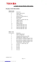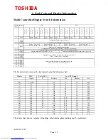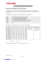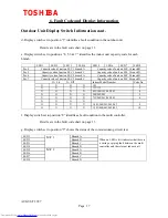
6. Fault Code and Display Information
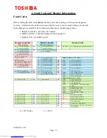
Fault Codes
Before reading the fault codes
do not
turn the power off as doing so will wipe the diagnostic
memory. Caution must be taken when removing the access covers as high voltages are present.
Fault diagnosis is available at three locations within the air conditioning system :-
1. Remote Controller - press the check button
2. Multi Controller - rotate the display switch to position 1
3. Outdoor Unit - see following text
Phase Rotation, DOL HP Trip, O/Load,
Comp Klixon
î
Inv HP Trip, Comp Klixon
m
mm-
è
Refer To O/D
21
è
Refer to O/D
21
ThE Sensor Fault
è
Refer to O/D
18
è
Refer to O/D
18
High Inverter Current ac
m
m-m
è
Refer to O/D
1F
è
Refer to O/D
1F
High Inverter Current dc
m
-mm
è
Refer to O/D
1d
è
Refer to O/D
1d
Low Inverter Voltage
-
mmm
è
Refer to O/D
14
è
Refer to O/D
14
SW01 Set to Off/Off
Low Pressure <3.5psig
LED8
Suction Pipe >40ºC
LED7
Discharge Pipe >130ºC
LED6
Pressure Sensor Fault
LED5
High Pressure - detected by pressure
sensor
LED4
ThS Sensor Fault
LED3
ThD2 Sensor Fault
LED2
ThD1 Sensor Fault
LED1
è
Refer to O/D
1C
è
Refer to O/D
1C
Display Switch set to “3” (if lit....)
M/C2 Sensor Fault
LED8
M/C1 Sensor Fault
LED7
ID Codes set to Zero
M/C Settings too High
LED6
ç
ID Codes too High
89
è
Preheat/Defrost Flash
M/C Water Level
ç
M/C Water Level
Ob
ì
Refer to Multi Con
15
Th(X) Sensor Fault
LED5
ç
Th(X) Sensor Fault
84
Th(D) Sensor Fault
LED4
ç
Th(D) Sensor Fault
83
No Communication
Indoor to Rem Con.
99
Th(C) Sensor Fault
LED3
ç
Th(C) Sensor Fault
82
Frost or no Change ºC
O9
Th(B) Sensor Fault
LED2
ç
Th(B) Sensor Fault
81
Reverse Change Temp
O8
Th(A) Sensor Fault
LED1
ç
Th(A) Sensor Fault
80
TC Sensor
Od
Display Switch set to “8” (if lit....)
No Communication
Initially M/C to OD
88
TA Sensor
OC
I.D. Water Level
Ob
No Communication
Indoor to Multi Con
O4
No Communication Multi
Con to Outdoor
O4
è
No Communication
Multi Con to Outdoor
O4
No Communication Inverter to Interface
see Table 1
è
No Communication
Inverter to Interface
O4
è
No Communication
Inverter to Interface
O4
Outdoor Unit
Multi Controller
Switch Position 1
Remote Controller
Press Check
-
= LED Flashing
m
= LED On
TOSHIBA
AUGUST 1997
Page 13

