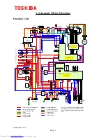
4. Schematic Wiring Diagrams
Outdoor Unit
1 2 3 4 5 6 7 8 9
1 2 3 4 5 6 7 8 9
1 2 3 4 5 6 7
1 2 3 4 5 6 7
1 2 3 1 2 3 1 2 3
1 2 3
1 2 3
1 2 3 4 5
1 2 3 4 5
1 2 3 4 5
5 4 3 2 1
1
2
3
4
5
6
7
3
2
1
1
2
3
3
2
1
Pressure
Sensor
1 2 3
1 2 3
1 2 3
U V W
W
V
U
+
-
+
-
1 2 3 4
1 2 3 4
1 2
(~)
(~)
(~)
3
ℜ
Noise Filter
1
ℜ
Noise
Filter
7 8 9 10 11 12
1 2 3 4 5 6 7 8 9
1 2 3 4 5 6 7 8 9
SV1
SV2
SV3
1 2 3 4
1 2
1 2 3 4
1 2
1 2 3 4 5 6
PMV1
FM2
FM1
1 2 3
1 2
1 2 3
1
ℜ
Noise
Filter
6
5
4
3
2
1
L1 L2 L3 N
1
2
3
1
2
2
1
1
2
3
4
W
V
U
CM2
CM1
Gate Drive PCB
MCC - 1252
CN21
P01
P02
CN24 CN23 CN22
CN25
CN2
INVERTER CONTROL
PCB
MCC - 1251
CN2
CN1
CN5
CN9
CN8
CN4
CD1
CN121
CN6
ThE
INTERFACE CONTROL
PCB
MCC - 1211
PJ5
P2
P1
PJ6
PJ1
WHI
PJ2
BLK
PJ3
BLU
ThD1 ThD2
ThS
PJ12
PJ16
PJ15
PJ7
PJ8
PJ11
PJ10
1
ℜ
Noise
Filter
CAPACITORS
2200
λ
F x 2
M/C (1)
M/C (2)
POWER SUPPLY
50Hz 3
ℜ
380/415 v
Display
Switch
Display LED x 8
Diode
Clipper
Diode
Clipper
CD2
CD2
Reactor
Rectifier
Electric Starter
Contactor
52C2
Contactor
52C1
Capacitor
1
λ
F x 3
Fuses
20A x 3
Crankcase
Heater
Inverter HP
Sw
63H1
Inverter Klixon
49C1
DOL Klixon
49C2
DOL HP Sw
63H2
Contactor
52C3
Return
Lock
Surge
Absorber
Surge
Absorber
Low Pressure
Switch 63L
R C 1
R C 2
Tr1
Tr2
Thermal Fuse
TRS
Giant
Transistor
Smoothing Circuit
2200
λ
F/400v x 2
47k
Ω
/20W x 2
1
2
3
Reversing
Valve
Fuses
2 x 7A
= 240 v ac Live (not permanent)
= dc high voltage live
= Neutral (not permanent)
= dc high voltage neutral
= Communication Signal
= 3Ø for Inv Compressor
= Earth
= dc low voltage
= L1 phase 415ac
= ac low voltage
= L2 phase 415ac
= ac low voltage
= L3 phase 415ac
Fuse 20A
20SF
Note :The colours used in this diagram are not
representative of those on the actual producct,
they are intended to indicate the status of each
wire.
Fan Motors
Solenoid Valves
Pulsed
Modulating
Valve
Inverter
Compressor
D.O.L.
Compressor
TOSHIBA
AUGUST 1997
Page 9


