background image

– 1 –

Installation Manual

EN-1

EN-2

Contents

1

Precautions for Safety. . . . . . . . . . . . . . . . . . . . . . . . . . . . . . . . . . . . . . . 1

2

Accessory Parts. . . . . . . . . . . . . . . . . . . . . . . . . . . . . . . . . . . . . . . . . . . . 3

3

Installation of New Refrigerant Air Conditioner . . . . . . . . . . . . . . . . . . 3

4

Installation Conditions  . . . . . . . . . . . . . . . . . . . . . . . . . . . . . . . . . . . . . . 4

5

Refrigerant Piping . . . . . . . . . . . . . . . . . . . . . . . . . . . . . . . . . . . . . . . . . . 7

6

Electric Wiring . . . . . . . . . . . . . . . . . . . . . . . . . . . . . . . . . . . . . . . . . . . . 16

7

Address Setting . . . . . . . . . . . . . . . . . . . . . . . . . . . . . . . . . . . . . . . . . . . 19

8

Test Run . . . . . . . . . . . . . . . . . . . . . . . . . . . . . . . . . . . . . . . . . . . . . . . . . 26

9

Troubleshooting. . . . . . . . . . . . . . . . . . . . . . . . . . . . . . . . . . . . . . . . . . . 29

ADOPTION OF NEW REFRIGERANT

This Air Conditioner uses R410A an environmentally friendly refrigerant.

1

Precautions for Safety

The manufacturer shall not assume any liability for the damage caused by not observing the description of this manual.

WARNING

General

• Before starting to install the air conditioner, read through the Installation Manual carefully, and follow its instructions to install 

the air conditioner. Otherwise, falling down of the unit may occur, or the unit may cause noise, vibration or water leakage.

• Only a qualified installer or qualified service person is allowed to do installation work. If installation is carried out by an

unqualified individual, a fire, electric shocks, injury, water leakage, noise and / or vibration may result.

• Do not use any refrigerant different from the one specified for complement or replacement. Otherwise, abnormally high 

pressure may be generated in the refrigeration cycle, which may result in a failure or explosion of the product or an injury to
your body.

• If using separately sold products, make sure to use Toshiba specified products only. Using unspecified products may cause 

fire, electric shock, water leak or other failure.

• Before opening the service panel of the outdoor unit, set the circuit breaker to the OFF position. Failure to set the circuit 

breaker to the OFF position may result in electric shocks through contact with the interior parts. Only a qualified installer or 
qualified service person is allowed to remove the service panel of the outdoor unit and do the work required.

• Before carrying out the installation, maintenance, repair or removal work, be sure to set the circuit breakers for both the

indoor and outdoor units to the OFF position. Otherwise, electric shock may result.

• Place a “Work in progress” sign near the circuit breaker while the installation, maintenance, repair or removal work is being 

carried out. There is a danger of electric shocks if the circuit breaker is set to ON by mistake.

• Only a qualified installer or qualified service person is allowed to undertake work at heights using a stand of 50 cm or more.
• When working at heights, use a ladder which complies with the ISO 14122 standard, and follow the procedure in the ladders 

instructions. Also wear a helmet for use in industry as protective gear to undertake the work.

• Wear protective gloves and safety work clothing during installation, servicing and removal.
• Do not touch the aluminium fin of the outdoor unit. You may injure yourself if you do so. If the fin must be touched for some 

reason, first put on protective gloves and safety work clothing, and then proceed.

• Do not climb onto or place objects on top of the outdoor unit. You may fall or the objects may fall off of the outdoor unit and 

result in injury.

• When working at height, put a sign in place so that no-one will approach the work location before proceeding with the work. 

Parts or other objects may fall from above, possibly injuring a person below. Also, be sure that workers put on helmets.

• When cleaning the filter or other parts of the outdoor unit, set the circuit breaker to OFF without fail, and place a “Work in 

progress” sign near the circuit breaker before proceeding with the work.

• The refrigerant used by this air conditioner is the R410A.
• You shall ensure that the air conditioner is transported in stable condition. If you find any part of the product broken, contact 

your dealer.

• Do not modify the products. Do not also disassemble or modify the parts. It may cause a fire, electric shock or injury.
• Before starting to repair the air conditioner, read carefully through the Service Manual, and repair the air conditioner by 

following its instructions.

• Only qualified service person is allowed to repair the air conditioner. Repair of the air conditioner by unqualified person may 

give rise to a fire, electric shocks, injury, water leaks and/or other problem.

• Once the repair work has been completed, check for refrigerant leaks, and check the insulation resistance and water 

drainage. Then perform a trial run to check that the air conditioner is running properly.

Selection of installation location

• If you install the unit in a small room, take appropriate measures to prevent the refrigerant from exceeding the limit 

concentration even if it leaks. Consult the dealer from whom you purchased the air conditioner when you implement the 
measures. Accumulation of highly concentrated refrigerant may cause an oxygen deficiency accident.

• Do not install the air conditioner in a location that may be subject to a risk of exposure to a combustible gas. If a combustible 

gas leaks and becomes concentrated around the unit, a fire may occur.

• When transporting the air conditioner, wear shoes with additional protective toe caps.
• When transporting the air conditioner, do not take hold of the bands around the packing carton. You may injure yourself if the


bands should break.

• Do not place any combustion appliance in a place where it is directly exposed to the wind of air conditioner, otherwise it may


cause imperfect combustion.

• Places where the operation sound of the outdoor unit may cause a disturbance. (Especially at the boundary line with a 

neighbour, install the air conditioner while considering the noise.)

• When transporting the air conditioner, use a forklift and when moving the air conditioner by hand, move the unit with 

4


people. 

Original instruction

2FAN_IM_DB04905901-00.book  Page 1  Friday, October 24, 2014  3:19 PM

Summary of Contents for MCY-MAP0401TP Series

Page 1: ...h AIR CONDITIONER MULTI TYPE Installation Manual For commercial use Outdoor Unit Model name MCY MAP0401TP Series MCY MAP0501TP Series MCY MAP0601TP Series 2FAN_IM_DB04905901 00 book Page 1 Friday October 24 2014 3 19 PM 1121701001 ...

Page 2: ...f if you do so If the fin must be touched for some reason first put on protective gloves and safety work clothing and then proceed Do not climb onto or place objects on top of the outdoor unit You may fall or the objects may fall off of the outdoor unit and result in injury When working at height put a sign in place so that no one will approach the work location before proceeding with the work Par...

Page 3: ...lt in fire When carrying out electric connection use the wire specified in the Installation Manual and connect and fix the wires securely to prevent them applying external force to the terminals Improper connection or fixing may result in fire Test run Before operating the air conditioner after having completed the work check that the electrical parts box cover of the indoor unit and service panel...

Page 4: ... enter Required tools and cautions on handling It is necessary to prepare the tools and parts for installation as described below The tools and parts which will be newly prepared in the following items should be restricted to exclusive use Explanation of symbols Newly prepared It is necessary to use it exclusively with R410A separately from those for R22 or R407C Former tool is available Used tool...

Page 5: ...oor unit Insufficient durability may cause the outdoor unit to fall which may result in injury This outdoor unit has a weight of about 74 kg or more Pay special attention when installing the unit onto a wall surface CAUTION Do not install the outdoor unit in a location that is subject to combustible gas leaks Accumulation of combustible gas around the outdoor unit may cause a fire Install the outd...

Page 6: ...ll the unit so that its discharge port faces the wall of the building Keep a distance 500 mm or more between the unit and wall surface 2 Leave a clearance of at least 250 mm between the right side panel and wall or other surface of the building for installation and servicing purposes 250 mm 3 Leave a clearance of at least 200 mm between the rear panel and wall or other surface of the building in o...

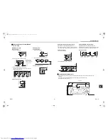
Page 7: ... and left of the unit The height of an obstacle in both the front and rear of the unit should be lower than the height of the outdoor unit Standard installation 1 Single unit installation 2 Serial installation of two or more units Serial installation in front and rear Open above and to the right and left of the unit The height of an obstacle in both the front and rear of the unit should be lower t...

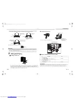
Page 8: ...utdoor unit connecting pipes can be connected in any of 4 directions Use a screwdriver to punch out the knockout part of the front panel side panel or base Wear heavy work gloves to protect yourself from injury while doing this work After punching out the knockout hole in a manner which ensures that the pipes and wires will not be damaged in any way remove the burrs from around the hole Optional i...

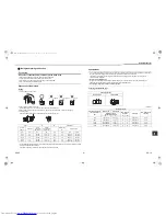
Page 9: ...1 0 to 1 5 16 6 26 49 to 61 4 9 to 6 1 15 88 1 0 0 to 0 5 1 0 to 1 5 19 7 29 63 to 77 6 6 to 7 7 90 Obliquity Roughness Warp A B REQUIREMENT For a brazing work of the refrigerant pipes be sure to use nitrogen gas in order to prevent oxidation of the inside of the pipes otherwise clogging of the refrigerating cycle due to oxidized scale may occur Use clean and new pipes for the refrigerant pipes an...

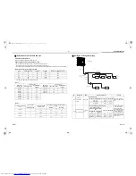
Page 10: ...oor unit capacity type Capacity code No of connectable indoor units Total capacity code of connectable indoor units Equivalent to HP Min HP Max HP 040 type 4 2 to 6 3 2 5 2 050 type 5 2 to 6 4 0 6 5 Selection of refrigerant piping No Piping parts Name Selection of pipe size Remarks 1 Outdoor unit 1st branching section Main pipe Size of main pipe Same as connecting pipe size of the outdoor unit 2 B...

Page 11: ...exceeds the capacity code of the outdoor unit apply the capacity code of the outdoor unit See Table 1 and 2 Outdoor unit capacity type Gas pipe Liquid pipe 0401 type 15 88 9 52 0501 type 15 88 9 52 Total capacity codes of indoor units at down stream side Gas pipe Liquid pipe Equivalent to HP Equivalent to capacity Below 2 4 Below 6 4 12 70 9 52 2 4 or more Below 6 4 15 88 9 52 0601 type 19 05 9 52...

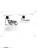
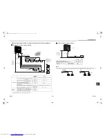
Page 12: ... outdoor unit 15 m Height between indoor units H2 10 m Outdoor unit 2FAN_IM_DB04905901 00 book Page 11 Friday October 24 2014 3 19 PM L2 L1 d L3 e f Y shaped branching joint Main pipe 1st branching pipe section Branching Branching header Indoor unit pipe Branching Heigh ce betweenindoorand outdoor units H1 Height erence units H2 betweenindoor Equivalent length corresponded to farthest piping after...

Page 13: ...units to one PMV Kit Arrange one indoor unit and one PMV Kit set to 1 by 1 NO GOOD OK PMV Kit PMV Kit Indoor unit Indoor unit EN 23 EN 24 2FAN_IM_DB04905901 00 book Page 12 Friday October 24 2014 3 19 PM l f a b c H2 H2 H2 L3 A 1 L1 L2 k g h i Height difference between indoor and outdoor units H1 Main pipe section 1st branching Branching pipe header Branching Indoor unit Y shaped branching joint B...

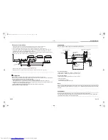
Page 14: ...anifold Outdoor unit Service port NOTE However if the environmental temperature changes from the moment of applying pressure to 24 hours after that the pressure will change by about 0 01 MPa 0 1 kg cm2 G per 1 C Consider the pressure change when checking the test result REQUIREMENT When pressure decrease is detected in steps 1 3 check the leakage at the connecting points Check the leakage using a ...

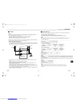
Page 15: ...t Low pressure guage High pressure guage Ball valve fully closed Gas side Flare connection Flare connection Packed valve fully closed Liquid side Service port Vacuum pump Gauge manifold Outdoor unit Service port Adding refrigerant After finishing vacuuming exchange the vacuum pump with a refrigerant canister and start additional charging of refrigerant Calculation of additional refrigerant charge ...

Page 16: ...L5 Ø6 35 3 m L6 Ø6 35 4 m L7 Ø6 35 5 m A MMU AP0154H B MMU AP0094H C MMU AP0074MH D MMD AP0074SPH L1 L2 L3 L4 L5 L6 L7 D C B A Full opening of the valve Open the valves of the outdoor unit fully Liquid side Using a 4mm hexagonal wrench fully open the valve rods Gas side Using a 5mm hexagonal wrench fully open the valve rods Heat insulation for pipe Apply heat insulation of pipe separately at the l...

Page 17: ...rd model MCA Maximum Circuit Amps MOCP Maximum Overcurrent Protection Amps Model Power Supply Nominal Voltage Phase and frequency MCA A MOCP A MCY MAP0401 220 240 V 50 Hz 27 0 32 0 MCY MAP0501 28 0 32 0 Circuit breaker Earth leakage breaker Main switch Fuse Specifications for communication wiring Design of communication wiring Summary of communication wiring Communication wiring and central contro...

Page 18: ...3 U4 U1 U2 U1 U3 U2 U4 U1 U2 A B U3 U4 U1 U2 U1 U2 A B U1 U2 A B U1 U2 A B U1 U2 A B U1 U2 A B U3 U4 U1 U2 U5 U6 U1 U2 A B U1 U2 A B U1 U2 A B U3 U4 U1 U2 U5 U6 L1 L5 L6 L6 L7 L7 L4 3 L 2 L Central controller This system Other system Table 1 Header unit Follower unit Table 1 Table 2 Table 3 Outdoor unit Indoor unit Remote controller Remote controller Remote controller Group control through a remot...

Page 19: ...Also apply insulating sleeves to the crimping parts Use a driver of appropriate size to fix the terminal screws Design 60245 IEC66 Screw size and tightening torque Wire size 4 0 mm2 Screw size Tightening torque N m Power supply terminal M6 2 5 3 0 Earth screw M6 2 5 3 0 EN 35 EN 36 2FAN_IM_DB04905901 00 book Page 18 Friday October 24 2014 3 19 PM Terminal block Earth screw Power supply Power suppl...

Page 20: ...g on the power Running the unit is not required for address setting The addresses can be set manually Automatic addressing setting addresses using SW15 on the interface P C board on the outdoor unit Manual addressing setting addresses on the wired remote controller When setting an address manually the wired remote controller must temporarily be paired with an indoor unit one to one when the system...

Page 21: ...P C board on the outdoor unit of each system Factory default Address 1 NOTE Be sure to set a unique address on each system Do not use a same address as another system refrigerant line or a custom side Example Controlling 2 or more refrigerant lines as a group System wiring diagram Auto 1 Auto 2 Auto 3 U 1 U 1 flash U 1 U 1 light 3 2 4 D600 D601 D602 D603 D604 SW04 SW05 SW15 SW01 SW02 SW03 Outdoor ...

Page 22: ...ted to the same central control except the unit that has the lowest address For unifying the termination of the wiring for the central control of indoor and outdoor units U1 U2 U3 U4 CN02 CN10 U1 U2 U3 U4 TO INDOOR UNIT TO CENTRAL CONTROLLER U1 U2 and U3 U4 not connected Communication terminal board U 1 L08 U 1 flash Auto 1 Auto 2 Auto 3 U 1 U 1 flash U 1 U 1 light 9 Connect the relay connectors C...

Page 23: ...e controller Group Individual Indoor units automatic setting Outdoor unit U1 U2 and U3 U4 connected Outdoor unit U1 U2 and U3 U4 connected Outdoor unit U1 U2 and U3 U4 connected Manual address setting with the remote controller Procedure when setting indoor units addresses first under the condition that indoor wiring has been completed and outdoor wiring has not been started manual setting using t...

Page 24: ...west address For unifying the termination of the wiring for the central control of indoor and outdoor units Connect the relay connectors CN10 between the U1 U2 and U3 U4 terminals on the interface P C board to CN02 in all the outdoor units to which the central control is connected After finishing all the settings above set the address of the central control devices For the setting of the central c...

Page 25: ...ne are indicated one after another Only the fan and louvers of the indicated indoor unit are activated UNIT LOUVER 5 6 1 3 4 2 ON OFF TEMP TIME SET CL FILTER RESET TEST TIMER SET CODENo UNIT No SETTING DATA SET R C No UNIT LOUVER SWING FIX UNIT LOUVER To select another system address 5 Push the button to return to step 2 After returning to step 2 select another system address and check the indoor ...

Page 26: ...n SET DATA 6 Push the button left side of the button repeatedly to select another address to change Each time you push the button the indoor unit numbers in a refrigerant line are indicated one after another Only the fan and louvers of the selected indoor unit are activated Repeat steps 4 to 6 to change the indoor unit addresses so as to make each of them unique 7 Push the button All the segments ...

Page 27: ...trol address U 1 A d buS A d nEt A d c L U 1 L08 A d n G 8 Test Run Before test run Confirm that the valve of the refrigerate pipe of the outdoor unit is OPEN Before turning on the power confirm that the resistance between the terminal block of power supply and the earth is more than 1 M τ using a 500 V megohmmeter Do not run the unit if it is less than 1 M τ CAUTION Turn on the power and turn on ...

Page 28: ... units connected are available Individual test run Starting operation 1 Set the running mode to COOL or HEAT on the remote controller of the indoor unit to be tested The unit will run in the current mode unless you set the mode otherwise 2 Set the rotary switches on the interface P C board of the outdoor unit SW01 to 16 SW02 and SW03 to the address of the indoor unit to be tested 3 Push and hold S...

Page 29: ...es after turning the power on or stopping running 7 segment display A U1 B 7 segment display A C H B 7 segment display A C H B C H Stop operation 1 Set the rotary switches on the interface P C board of the outdoor unit back SW01 to 1 SW02 to 1 and SW03 to 1 7 segment display A U1 B D600 D601 D602 D603 D604 SW04 SW05 SW15 SW01 SW02 SW03 Interface P C board Push switch 7 segment display A Push switc...

Page 30: ... F24 Pd sensor error F31 Outdoor EEPROM error H01 Compressor breakdown A B D600 D601 D602 D603 D604 H02 Compressor trouble Lock H03 Current detective circuit system error H06 Low pressure proctive operation L04 Outdoor system address duplicated L06 Number of indoor units with priority Duplication of indoor units with priority L08 Indoor group Address unset L10 Outdoor capacity unset L29 IPDU quant...

Page 31: ...s 0 3 kg m3 NOTE 1 If there are 2 or more refrigerating systems in a single refrigerating device the amounts of refrigerant should be as charged in each independent device For the amount of charge in this example The possible amount of leaked refrigerant gas in rooms A B and C is 10 kg The possible amount of leaked refrigerant gas in rooms D E and F is 15 kg Total amount of refrigerant kg Min volu...

Page 32: ......

Reviews: