background image

– 7 –

Outdoor Unit

Installation Manual

Outdoor Unit

Installation Manual

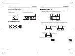
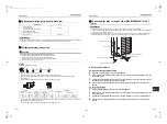
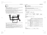
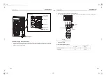
• When water is to be drained through the drain hose, attach the following drain nipple and waterproof rubber cap, 

and use the drain hose (Inner diam: 16 mm) sold on the market. Also seal the knockout hole and screws securely 
with silicone material, etc., to prevent water from leaking.
Some conditions may cause dewing or dripping of water.

• When collectively draining discharged water completely, use a drain pan.

• Please pay attention to the drain in region with snowfall and cold temperature, as it may be frozen and cause 

drainage problems. Punch the knockout holes on the bottom plate to improve drainability. Use a screwdriver and 
take off the knockout part outward.

For reference

If a heating operation is to be continuously performed for a long time under the condition that the outdoor 
temperature is 0 °C or lower, draining defrosted water may be difficult due to the bottom plate freezing, resulting in 
trouble with the cabinet or fan.
It is recommended to procure an anti-freeze heater locally in order to safely install the air conditioner.
For details, contact the dealer.

Waterproof rubber cap

Drain nipple

Knockout hole

Waterproof rubber cap

Drain nipple

5

Refrigerant piping

Knockout of pipe cover

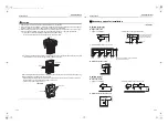
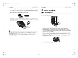
Knockout procedure

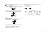
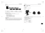
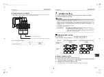
• The indoor / outdoor connecting pipes can be connected in 4 directions.

Take off the knockout of the pipe cover or bottom plate where the pipes or wires will pass through.

• Without detaching the pipe cover, tap on the knockout section a few times with the shank of a screwdriver. A 

knockout hole can easily be punched.

• As shown in the figure below, it is easier to punch out the knockout hole when the pipe cover is left in place rather 

than when the cover is removed from the unit.
In knocking out the hole, the knockout section can easily be removed by hand once the bottom of the three 
locations where the section is joined along the guide lines is broken using a screwdriver.

• After punching out the knockout hole, remove burrs from the hole, and install the protective bush and guard 

material around the passage hole provided as accessories in order to protect the wires and pipes. Also be sure 
to attach the pipe covers after connecting the pipes. The pipe covers can be easily attached by cutting off the 
slits at the lower part of the covers.

* Be sure to wear heavy work gloves while working.

Rear

Side

Bottom

Pipe cover

Front

13-EN

14-EN

+00EH99883601_00Ta.book  Page 7  Thursday, September 8, 2011  4:34 PM

Summary of Contents for MCY-MAP0604HT7

Page 1: ...T8 MCY MAP0604HT7 MCY MAP0804HT7 Installation Manual For commercial use Para uso comercial Para utilização comercial 商业用途 安装说明书 91 简体中文 Installation Manual 1 English Manual de instalação 61 Português Manual de instalación 31 Español 00EH99883601_00Ta book Page 1 Thursday September 8 2011 4 34 PM ...

Page 2: ...s of the outdoor unit set the circuit breaker to OFF without fail and place a Work in progress sign near the circuit breaker before proceeding with the work When working at heights put a sign in place so that no one will approach the work location before proceeding with the work Parts and other objects may fall from above possibly injuring a person below The refrigerant used by this air conditione...

Page 3: ...it are closed and set the circuit breaker to the ON position You may receive an electric shock if the power is turned on without first conducting these checks When you have noticed that some kind of trouble such as when an error display has appeared there is a smell of burning abnormal sounds are heard the air conditioner fails to cool or heat or water is leaking has occurred in the air conditione...

Page 4: ...prevent mixing of refrigerant or refrigerating oil the size of the charge port of the main unit or connecting section of the installation tool differs to that of an air conditioner for the former refrigerant Accordingly exclusive tools are required for the new refrigerant R410A as shown below For connecting pipes use new and clean piping materials so that water or dust does not enter Required tool...

Page 5: ...ints from customers Installation location WARNING Install the outdoor unit properly in a location that is durable enough to support the weight of the outdoor unit Insufficient durability may cause the outdoor unit to fall which may result in injury This outdoor unit has a weight of about 125 kg Pay special attention when installing the unit onto a wall surface CAUTION Do not install the outdoor un...

Page 6: ... may be heavy take steps to prevent the unit from being adversely affected by the fallen or accumulated snow Either make the foundation higher or install a stand which is high enough to ensure that the unit will be above the fallen or accumulated snow and place the unit on it Attach a snow shield locally procured 500 mm Strong wind Strong wind Snow shield Snow shield Example Necessary space for in...

Page 7: ...gth and horizontalness of the base so that abnormal sounds do not emanate According to the following base diagram fix the base firmly with the anchor bolts Anchor bolt nut M10 x 4 pairs As shown in the figure below install vibration proof rubber pads to directly support the bottom surface of the fixing leg When installing the foundation for an outdoor unit with downward piping consider the piping ...

Page 8: ...erproof rubber cap Drain nipple Knockout hole Waterproof rubber cap Drain nipple 5 Refrigerant piping Knockout of pipe cover Knockout procedure The indoor outdoor connecting pipes can be connected in 4 directions Take off the knockout of the pipe cover or bottom plate where the pipes or wires will pass through Without detaching the pipe cover tap on the knockout section a few times with the shank ...

Page 9: ...m kgf m 9 5 0 8 0 to 0 5 1 0 to 1 5 13 2 22 33 to 42 3 3 to 4 2 19 1 1 2 0 to 0 5 1 0 to 1 5 24 0 36 100 to 120 10 0 to 12 0 Obliquity Roughness Warp 90 A B Connecting the pipe at the gas side MCY MAP0804HT8 HT7 only REQUIREMENT Connecting the main pipe Ø19 1 directly to the gas valve Ø19 1 may lower the performance To connect the main pipe Ø22 2 to the gas valve Ø19 1 use the joint pipe Ø19 1 Ø22...

Page 10: ... flare pipe connecting sections that connect the indoor outdoor units at the specified tightening torque Incomplete connections may cause not only a gas leak but also trouble with the refrigeration cycle Do not apply refrigerant oil to the flared surface Internally threaded side Externally threaded side Flare nut Tighten with torque wrench Fix with wrench Half union or packed valve Piping valve Ca...

Page 11: ... 4 8 7 8 0804 type 8 2 to 8 6 4 10 4 Selection of refrigerant piping No Piping parts Name Selection of pipe size Remarks 1 Outdoor unit 1st branching section Main pipe Connecting pipe size of outdoor unit Same as connecting pipe size of the outdoor unit 2 Branching section Branching section Branching pipe Pipe size between branching sections Pipe size differs based on the total capacity code value...

Page 12: ... size differs based on the total capacity code value of indoor units at the downstream side If the total value exceeds the capacity code of the outdoor unit apply the capacity code of the outdoor unit See Table 1 and 2 3 Branching section Indoor unit Indoor unit connecting pipe Connecting pipe size of indoor unit Indoor unit Main pipe Gas pipe 1st branching section Outdoor unit 5 2 4 1 3 Liquid pi...

Page 13: ...to be named A Allowable value Pipes Piping Length Total extension of pipe liquid pipe real length 100 m L1 L2 L3 L4 a b c d e f g Farthest piping length L 1 Real length 50 m L1 L3 L4 g Equivalent length 60 m Max real length of main pipe 30 m L1 Max real length of furthest piping from 1st branching Li 1 20 m L3 L4 g Max real length of indoor unit connecting pipe 10 m a b c d e f g Height Difference...

Page 14: ... m h i j k l m n Height Difference Height between indoor and outdoor units H1 Upper outdoor unit 15 m Lower outdoor unit 15 m Height between indoor unit and PMV kit H2 10 m e f l m n g a b h i j k c d H2 H2 H2 A 1 Branching pipe Height difference between indoor and outdoor units H1 1st branching section Outdoor unit Branching header L3 Main pipe L1 Y shape branch joint L4 Branching pipe L2 Equival...

Page 15: ...discharge gas side and liquid side REQUIREMENT Do not use Oxygen Flammable gas and Noxious gas in an airtight test To detect a gross leakage 1 Apply pressure 0 3 MPa 3 0 kg cm2 G for 3 minutes or more 2 Apply pressure 1 5 MPa 15 kg cm2 G for 3 minutes or more To detect a slow leakage 3 Apply pressure 3 73 MPa 38 kg cm2G for approx 24 hours Check pressure down No pressure down Accepted Pressure dow...

Page 16: ...s finished exchange the vacuum pump with a refrigerant cylinder and advance to the additional charging of refrigerant Main pipe Brazed Fully closed Ball valve fully closed gas side Outdoor unit Service port Service port Packed valve fully closed liquid side Gauge manifold High pressure guage Low pressure guage Connected to indoor unit Vacuum pump Adding refrigerant After finishing vacuuming exchan...

Page 17: ...Ly Real total length of liquid pipe Ø9 5 m a Corrective amount of refrigerant depending on the unit A kg b Corrective amount of refrigerant depending on the unit B kg c Corrective amount of refrigerant depending on the unit C kg d Corrective amount of refrigerant depending on the unit D kg L1 L2 L3 L4 L5 L6 L7 A B C D How to open the valve Open or close the valve Liquid side Open the valve with a ...

Page 18: ...manual of each indoor unit Power wiring selection Standard model MCA Maximum Circuit Amps MOCP Maximum Overcurrent Protection Amps Model Power Supply MCA A MOCP A Phase and frequency Nominal Voltage MCY MAP0604HT8 MCY MAP0804HT8 3N 50 Hz 380 415 V 16 5 25 MCY MAP0604HT7 MCY MAP0804HT7 3N 60 Hz 380 V 16 5 25 Circuit breaker earth leakage breaker Main switch fuse Specifications for communication wir...

Page 19: ...U1 U2 A B U3 U4 U1 U2 U1 U2 A B U1 U2 A B U1 U2 A B U1 U2 A B U1 U2 A B U3 U4 U1 U2 U5 U6 U1 U2 A B U1 U2 A B U1 U2 A B U3 U4 U1 U2 U5 U6 L1 L5 L6 L6 L7 L7 L4 L2 L3 Header unit Follower unit S MMS Super modular multi system Central controller Outdoor unit Indoor unit Table 1 Table 2 Table 1 Remote controller Remote controller Remote controller Table 3 MiNi SMMS Group control through a remote contr...

Page 20: ...d clamps Communication terminal block Protective bush accessory Earth screw Power supply wires Communication wires 2 Use round type crimping terminals for power connection Also apply insulating sleeves to the crimping parts Use a driver of appropriate size to fix the terminal screws Design 60245 IEC66 Screw size and tightening torque Wire size 2 5 mm2 Screw size Tightening torque N m Power supply ...

Page 21: ...or address setting The addresses can be set manually Automatic address setting Address setting procedure 1 1 Turn on indoor units first and then turn on outdoor units 2 About one minute after turning the power on confirm that the 7 segment display on the interface P C board of the outdoor unit indicates 3 Press SW 15 to start the automatic address setting It may take up to 10 minutes normally abou...

Page 22: ...interface P C board on the outdoor unit of each system factory default Address 1 NOTE Be sure to set a unique address on each system Do not use a same address as another system refrigerant line or a custom side Example Controlling 2 or more refrigerant lines as a group System wiring diagram Auto 1 Auto 2 Auto 3 U 1 U 1 flash U 1 U 1 light SW04 SW05 SW15 SW01 SW02 SW03 D600 D601 D602 D603 D604 3 2 ...

Page 23: ...to 6 for other refrigerant lines 8 After completing address setting of all systems turn off dip switch 2 of SW30 on the interface P C boards of all the outdoor units connected to the same central control except the unit that has the lowest address For unifying the termination of the wiring for the central control of indoor and outdoor units U1 U2 U3 U4 2 To indoor unit To central controller U 1 L0...

Page 24: ...t Outdoor unit Outdoor unit Remote controller Remote controller Remote controller Remote controller Individual Group Indoor units automatic setting Manual address setting with the remote controller Procedure when setting indoor units addresses first under the condition that indoor wiring has been completed and outdoor wiring has not been started manual setting using the remote controller Wiring ex...

Page 25: ...entral control except the unit that has the lowest address For unifying the termination of the wiring for the central control of indoor and outdoor units Connect the relay connectors between the U1 U2 and U3 U4 terminals on the outdoor unit of each refrigerate line After finishing all the settings above set the address of the central control devices For the setting of the central control address r...

Page 26: ...ected refrigerant line are indicated one after another Only the fan and louvers of the indicated indoor unit are activated VENT TEST TEST 5 6 1 3 4 2 ON OFF TEMP TIME SET CL FILTER RESET TEST TIMER SET CODENo UNIT No SETTING DATA SET R C No TEST SWING FIX SET To select another system address 5 Push the button to return to step 2 After returning to step 2 select another system address and check the...

Page 27: ... SET DATA to that of a new address 5 Push the button to confirm the new address on SET DATA 6 Push the button left side of the button repeatedly to select another address to change Each time you push the button the indoor unit numbers in a refrigerant line are indicated one after another Only the fan and louvers of the selected indoor unit are activated Repeat steps 4 to 6 to change the indoor uni...

Page 28: ...4 ON for more than five seconds Central control address 8 Test run Before test run Confirm that the valve of the refrigerate pipe of the outdoor unit is OPEN Before turning on the power confirm that the resistance between the terminal block of power supply and the earth is more than 1 M using a 500 V megohmmeter Do not run the unit if it is less than 1 M CAUTION Turn on the power and turn on the c...

Page 29: ...ive test run which tests all the indoor units connected are available Individual test run Starting operation 1 Set the running mode to COOL or HEAT on the remote controller of the indoor unit to be tested The unit will run in the current mode unless you set the mode otherwise 2 Set the rotary switches on the interface P C board of the outdoor unit SW01 to 16 SW02 and SW03 to the address of the ind...

Page 30: ...You cannot change the temperature setting during the test run Errors are detected as usual The unit does not perform test run for 3 minutes after turning the power on or stopping running A U1 B 7 segment display A C H B 7 segment display A C H B C H 7 segment display Stop operation 1 Set the rotary switches on the interface P C board of the outdoor unit back SW01 to 1 SW02 to 1 and SW03 to 1 A U1 ...

Page 31: ...2 TS sensor error F13 TH sensor Board installed error F15 Outdoor temp sensor miswiring TE TL F16 Outdoor pressure sensor miswiring Pd Ps F23 Ps sensor error F24 Pd sensor error F31 Outdoor EEPROM error H01 Compressor breaking down H02 Compressor error Locked H03 Current detection circuit error H05 TD sensor miswiring D600 A B D601 D602 D603 D604 1PDU number information 01 Compressor 08 Fan 09 Com...

Page 32: ...g m3 NOTE 1 If there are 2 or more refrigerating systems in a single refrigerating device the amounts of refrigerant should be as charged in each independent device For the amount of charge in this example The possible amount of leaked refrigerant gas in rooms A B and C is 10 kg The possible amount of leaked refrigerant gas in rooms D E and F is 15 kg NOTE 2 The standards for minimum room volume a...

Reviews: