162
Step Component
Procedure
Remarks
11
Fan motor
replacement
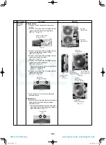
1) Remove the front panels, upper panel, and
discharge cabinets, and fan motor leads.
[Step.1, Step.2, and “2)” of Step.5]
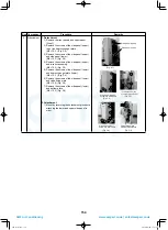
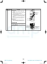
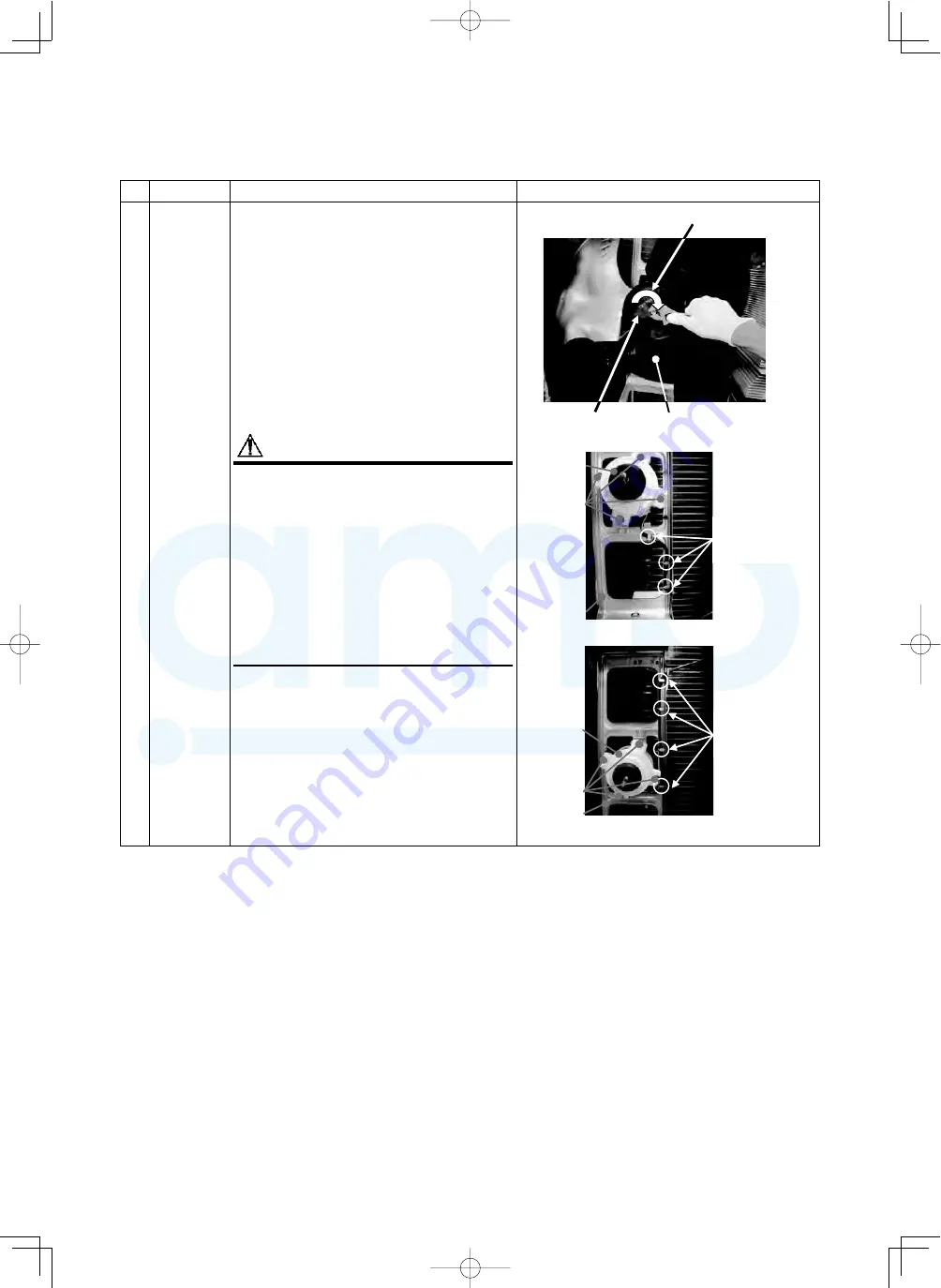
2) Remove the fl ange nut fi xing the fan motor and
propeller fan. (Fig. 11-1)
• Turn the flange nut clockwise to loosen it.
(To tighten it, turn it counterclockwise.)
3) Remove the propeller fan.
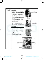
4) Remove the fan motor leads from the motor
base. (Fig. 11-2, 11-3)
5) Hold the fan motor and remove the 4 fi xing
screws so that the fan motor does not fall off.
(Fig. 11-2, 11-3)
6) Mount a new fan motor.
CAUTION
• Note that the wiring paths of the motor bases
(upper and lower) are different.
Also, make sure to arrange the lead wires
such that water cannot get inside the
mechanical compartment.
• Tighten the fl ange nut by 4.9 N•m
(50 kgf•cm).
• Adjust the length of the fan motor leads at
the inverter box to take up any excess slack
and ensure that the fan motor leads do not
come in contact with the propeller fan.
• Be careful so that the heat exchanger and
fan motor lead do not come into contact.
Flange nut
(Fig. 11-1)
Turn the flange nut clockwise to loosen it.
Propeller fan
Fan motor (upper)
Hooks
(4 positions)
Screws
(4 positions)
(Fig. 11-3)
Motor base
Fan motor
Fan motor (upper)
Hooks
(3 positions)
(Fig. 11-2)
Screws
(4 positions)
Motor base
Fan motor
A10-1510.indb 162
A10-1510.indb 162
2016/04/08 17:21:25
2016/04/08 17:21:25
AMP Air Conditioning
www.ampair.co.uk | sales@ampair.co.uk


