165
Step Component
Procedure
Remarks
14
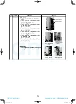
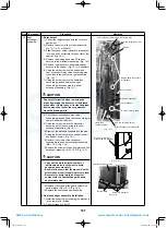
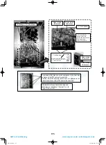
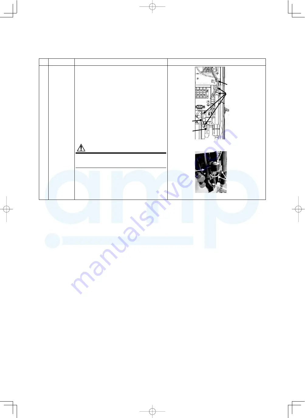
PMV coil
1. Detachment
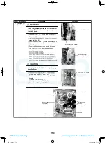
1) Remove the front panels, and upper panel.
[Step.1]
2) Remove the connector connected between the
interface P.C. board and PMV coil.
CN300 ...PMV coil (6P: white)
3) Remove the lead wire from the lead wire clamp
(1 position) and the banding band (3 places).
(Fig 14-1)
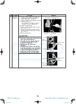
4) Rotate the coil, and remove while pulling it up
after the fi ngernail is removed. (Fig. 14-2)
2. Attachment
1) Match the positioning extrusion of the coil
surely to the concavity of PMV body to fi x it.
CAUTION
Using a banding band on the market, be sure
to fi x the lead wire.
PMV body
Banding band
(4 positions)
PMV coil
Lead wire clamp
(1 position)
(Fig. 14-2)
PMV coil
PMV body
(Fig. 14-1)
Rotate the coil, and
remove while pulling
it up after the
fingernail is removed.
Attach the
PMV coil lead
wires so they
face the left
side of the set.
A10-1510.indb 165
A10-1510.indb 165
2016/04/08 17:21:26
2016/04/08 17:21:26
AMP Air Conditioning
www.ampair.co.uk | sales@ampair.co.uk

