85
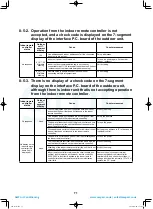
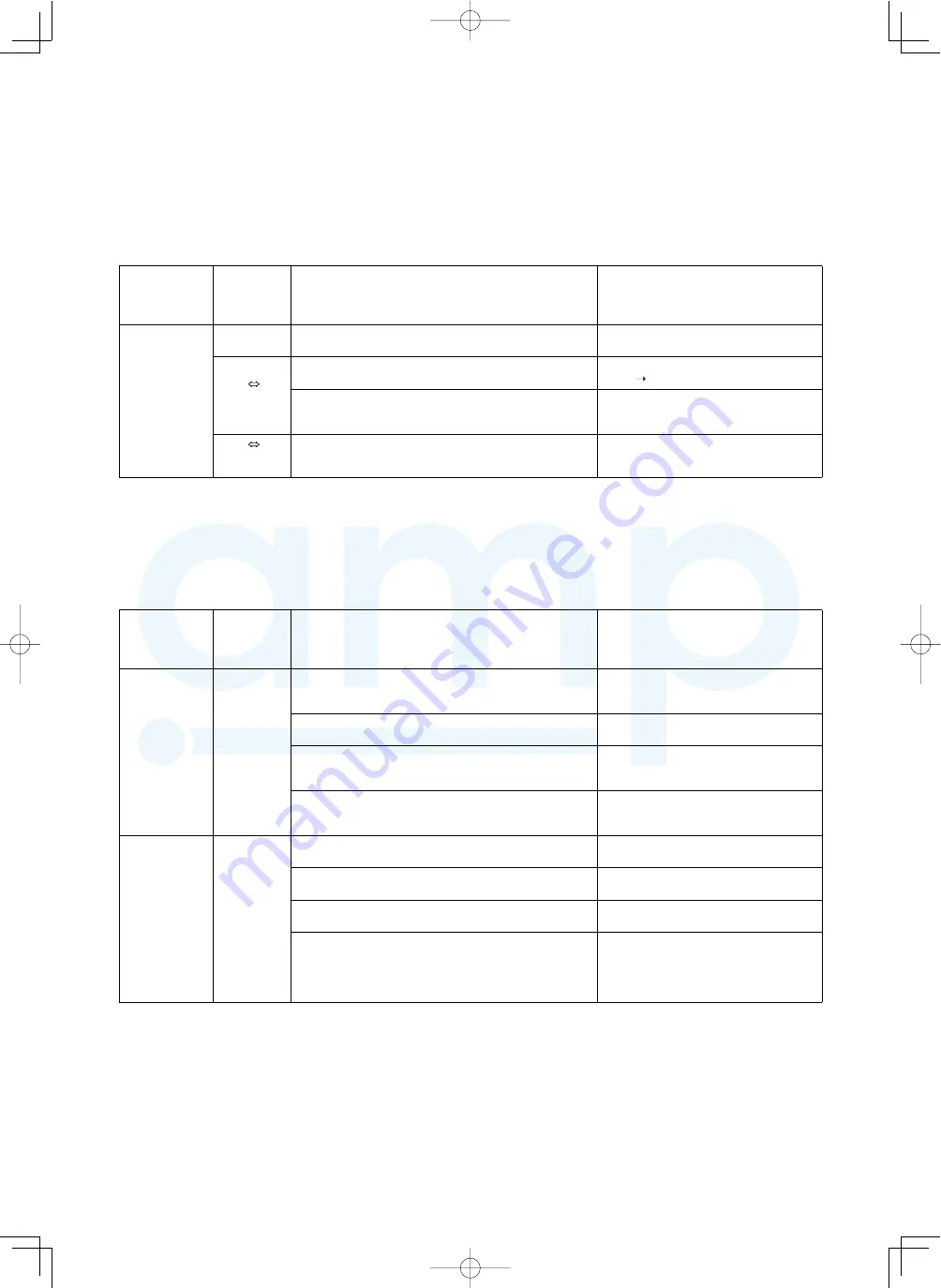
8-5-2. Operation from the indoor remote controller is not
accepted, and a check code is displayed on the 7-segment
display of the interface P.C. board of the outdoor unit.
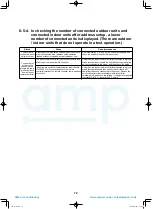
8-5-3. There is no display of a check code on the 7-segment
display on the interface P.C. board of the outdoor unit,
although there is indoor unit that is not accepting operation
from the indoor remote controller.
Indoor remote
controller
status
Outdoor
unit 7-
segment
display
s
e
r
u
s
a
e
m
r
e
t
n
u
o
C
e
s
u
a
C
No response
L08
Line addresses and indoor addresses of all the connected
indoor units are not set.
Set up addresses.
E19
-00
Alternate
blinking
:
r
e
d
r
o
e
h
t
n
I
(
.
n
i
a
g
a
r
e
w
o
p
e
h
t
n
o
n
r
u
T
.
n
o
d
e
n
r
u
t
t
o
n
s
i
r
e
w
o
p
t
i
n
u
r
o
o
d
n
I
indoor
outdoor)
Indoor / outdoor communication line is not correctly
connected to the U1 / U2 terminal of the outdoor unit. (Indoor
/ outdoor cannot communicate before address setup.)
Correct wiring
E20
-01
Alternate
blinking
Address setup is performed under the condition of
connecting multiple refrigerant lines.
Correct wiring
Indoor remote
controller
status
Outdoor
unit 7-
segment
display
s
e
r
u
s
a
e
m
r
e
t
n
u
o
C
e
s
u
a
C
No response
None
The communication line is not connected between indoor
and outdoor (the unit that does not respond to the indoor
remote controller).
Modify the wiring.
Line address and indoor address are not set (the unit that
does not respond to the indoor remote controller).
Set up the address.
The power of the outdoor unit of the group is not turned on in
indoor group control (the unit that does not respond to the
indoor remote controller).
Turn on the power.
Group address is set to the follower unit for individual control
(the unit that does not respond to the indoor remote
controller).
Set the group address to “0” in the case of
individual control.
No display on the
indoor remote
controller (No
frame line is
displayed.)
None
The power is not turned on (the unit that is not displayed on
the indoor remote controller).
Turn on the power.
The indoor remote controller is not connected with a wire (the
unit that is not displayed on the indoor remote controller).
Modify the wiring.
Miswiring of the indoor remote controller (the unit that is not
displayed on the indoor remote controller)
Modify the wiring.
Indoor remote controller communication circuit trouble (the
unit that is not displayed on the indoor remote controller)
If 220-240 V is incorrectly applied to the indoor remote
controller terminal, the remote controller communication
circuit fails.
Remove the quick connect terminal
connected to indoor remote controller
terminals A / B, and check the voltage. If
voltage is not applied (normally 15 to 18 V),
replace the P.C. board.
71
A10-1510.indb 71
A10-1510.indb 71
2016/04/08 17:20:58
2016/04/08 17:20:58
AMP Air Conditioning
www.ampair.co.uk | sales@ampair.co.uk

