104
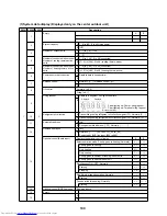
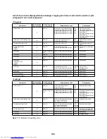
(5)Outdoor unit data display (Displayed only on the center outdoor unit)
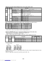
Note:
The indoor address is set by SW02 and SW03 switch, and displayed in 7-segment display A.
* Up to 48 indoor units can be connected to the same refrigerant piping line.
(6)Outdoor EEPROM writing error code display (Displayed only on the center unit)
* Displays the latest error code written on EEPROM of each outdoor unit.
(Used to check the error code after the power is reset.)
Set SW01 – SW03 as follows and press SW04 for 5 seconds or longer to display the error code:
• 7-segment display
Set [SW01 / SW02 / SW03] to [1 / 1 / 16] and press SW04 for 5 seconds or longer to display the latest error code
of the center unit (U1).
If SW02 is changed later, the latest error code of the center unit (U2 – U4).
SW01 SW02 SW03
Description
4
1 to 16
1 to 4
Indoor BUS communication
reception status
B When received: [… … 1], When not received: [… … …]
5
Indoor check code
B When there is no check code: [– – –]
6
Indoor horse power
B 0.2, 0.5, 0.8, …1, 1.2, 1.7, …2, 2.5, …3, 3.2, …4, …5, …6, …8, 1 0, 1 6, 2 0
7
Indoor request order
(S code, operation mode)
B [ #. …
]
#: Replaced with operation mode
Cooling: [C. …
], Heating: [H. …
]
Fan: [F. …
], Stop: [S. …
]
: Replaced with S code [#. … 0] to [#. … F]
8
Indoor PMV data
B Displays data in decimal
9
Indoor TSA sensor data
B Displays data in decimal
11
1 to 4
Indoor TCJ sensor data
B Displays data in decimal
12
Indoor TC1 sensor data
B Displays data in decimal
13
Indoor TC2 sensor data
B Displays data in decimal
SW03
SW02
Indoor address
7-segment display A
1
1 to 16
SW02 setting No.
[01] to [16]
2
1 to 16
SW02 setting No. + 16
[17] to [32]
3
1 to 16
SW02 setting No. + 32
[33] to [48]
4
1 to 16
SW02 setting No. + 48
[49] to [64]
SW01
SW02
SW03
Description
7-segment display
A
B
1
1
16
Latest error code of center unit (U1)
E. 1.
2
Latest error code of terminal unit 1 (U2)
E. 2.
3
Latest error code of terminal unit 2 (U3)
E. 3.
4
Latest error code of terminal unit 3 (U4)
E. 4.
Display A
Display B
Summary of Contents for MD-VNK802HEXE
Page 120: ...118 11Owner s Manual Excerpt ...
Page 137: ...135 12Installation Manual Excerpt ...


