167
Installation Manual
3
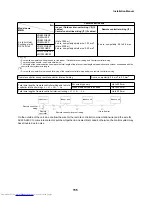
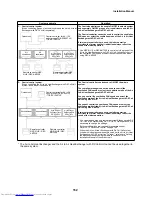
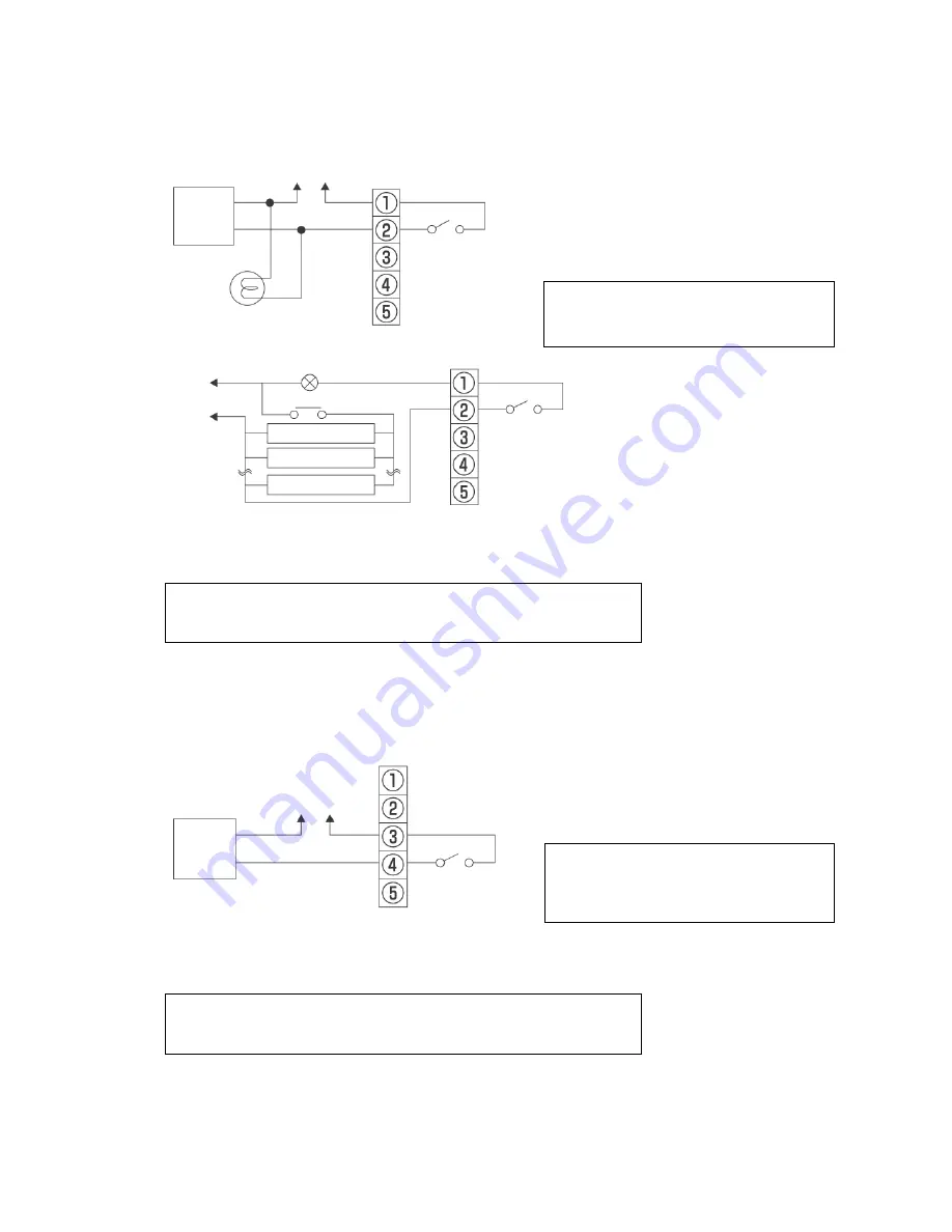
Connecting an auxiliary fan or monitoring operation output (External Output)
Connect to the terminal block for external output (1 and 2) in the electrical control box
Connection wire (locally procured): 2-core wire (H07 RN-F or 60245 IEC 66) 1.0 mm
2
to 2.5 mm
2
Contact is on during normal operation as factory default.
• Contact is off during nighttime heat purge operation or while fan operation is off to protect the unit.
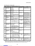
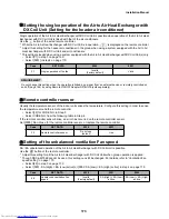
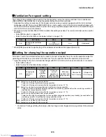
• The operation output settings can be changed. Refer to “Setting for changing the operation output” on
page 175.
4
Connecting an electric damper (electric shutter) (External Output)
Connect to the terminal block for external output (3 and 4) in the electrical control box
Connection wire (locally procured): 2-core wire (H07 RN-F or 60245 IEC 66) 1.0 mm
2
to 2.5 mm
2
Rated contact
Maximum: 240 VAC, 1 A
Minimum: 220 VAC, 100 mA
24 VDC, 1 A
5 VDC, 100 mA
Rated contact (3 to 5: Total value with abnormal signal output)
Maximum: 240 VAC, 1 A
Minimum: 220 VAC, 100 mA
24 VDC, 1 A
5 VDC, 100 mA
Power supply
Contact
Auxiliary
fan
Terminal block for external output
Lamp or management device
Terminal block for external output
If external devices is used working at a higher
voltage and current than the rated values, install
a relay according to the diagram below.
Rated relay: 220-240 VAC
To power supply
Relay contact
External device
Contact
External device
External device
220-240 V~, 50 Hz
220 V~, 60 Hz
Power supply
Contact
Electric
damper
Terminal block for external output
If external output is used working at a higher
voltage and current than the rated values, install
a relay according to the diagram above (diagram
for connecting an auxiliary fan).
Rated relay: 220-240 VAC
220-240 V~, 50 Hz
220 V~, 60 Hz
Summary of Contents for MD-VNK802HEXE
Page 120: ...118 11Owner s Manual Excerpt ...
Page 137: ...135 12Installation Manual Excerpt ...


