197
51
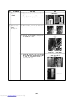
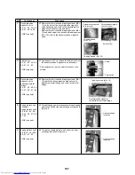
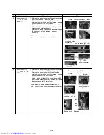
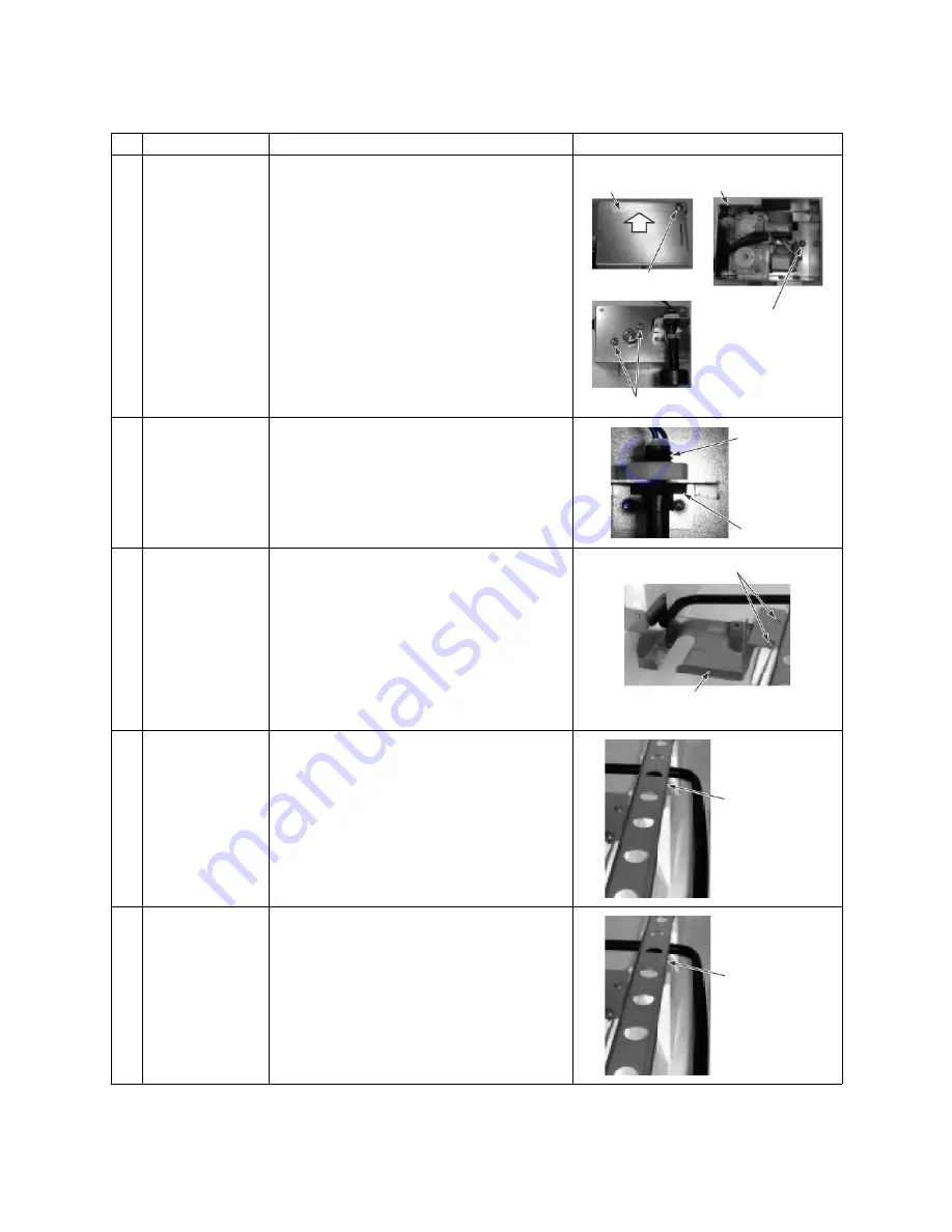
Decompression
magnetic valve
40., 41., 48., 49., 54.,
55., 57., 60. to 62.
<VNK type only>
62. Remove the two truss head tapping screws (M4 ×
10) on the side of the decompression magnetic
valve assembly, and remove the decompression
magnetic valve covers (up and side).
Remove the two truss head tapping screws (M4 ×
10) and earth screw (one truss head tapping screw
(M4 × 10)) that fix the decompression magnetic
valve.
52
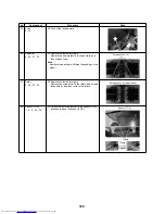
Float switch
40., 41., 48., 49., 54.,
55., 57., 61., 63.
<VNK type only>
63. Use a spanner (17) to remove the float switch from
the decompression magnetic valve assembly.
* After replacement, put the paint for plastic on the
screws.
53
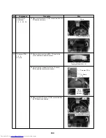
Decompression
magnetic valve
attachment metal
fittings
40., 41., 48., 49., 54.,
55., 57., 60., 61., 64.
<VNK type only>
64. Remove the two truss head tapping screws (M4 ×
10) that fix the decompression magnetic valve
attachment metal fittings, and remove the metal
fittings.
54
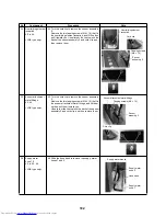
Supply water hose
assembly
Supply water hose 4
40. to 42., 44., 48.,
49., 54., 55., 57., 60.,
61., 65.
<VNK type only>
65. Thread the supply water hose assembly and supply
water hose 4 under the heat exchange reception to
remove it.
55
Supply water hose 3
40. to 42., 46. to 49.,
55., 57., 61., 66.
<VNK type only>
66. Thread the supply water hose 3 under the heat
exchange reception to remove it.
No.
Component
Procedure
Note
Decompression magnetic
valve cover (up)
Decompression magnetic
valve cover (side)
Tapping screws
(M4 × 10)
Tapping screws (M4 × 10)
Earth screw
Screw
Float switch
Tapping screws (M4 × 10)
Decompression magnetic
valve attachment metal fittings
Heat exchange
reception
Heat exchange
reception
Summary of Contents for MD-VNK802HEXE
Page 120: ...118 11Owner s Manual Excerpt ...
Page 137: ...135 12Installation Manual Excerpt ...


