199
60
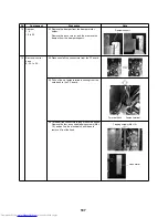
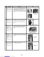
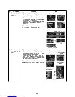
Sensor assembly 2
1., 2., 5., 40. to 45.,
48., 49., 71.
71. Remove the sensor assembly 2 connector coming
from the cord bush to the PC board.
Remove the sensor assembly 2 cord from the
electrical box clamp and from the clamp in the main
unit on the back of the electrical box.
Remove the two truss head tapping screws (M4 ×
10), and hook the sensor line metal fittings onto the
main unit bends (left and right).
Remove the clamp of the sensor line metal fittings
(2 positions), and then remove the sensor
assembly 2.
* When attaching, keep a distance of approximately
50 mm between the black tube and clamp.
61
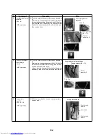
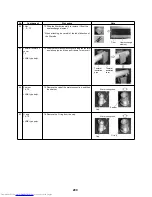
Sensor assembly 3
1., 2., 5., 40., 41., 48.,
49., 72.
72. Remove the sensor assembly 3 connector coming
from the cord bush to the PC board.
Remove the sensor assembly 3 cord from the
electrical box clamp and from the clamp in the main
unit on the back of the electrical box.
Use a nipper or the like to remove the banding
band (3 positions) that fix the sensor assembly 3
from the evaporator assembly, and then pull down
the sensor assembly 3 to remove it.
* When attaching, match up the colors of the PC
board connector and sensor assembly 3 connector.
No.
Component
Procedure
Note
Clamp
Sensor assembly 2 (Green)
Clamp
Clamp in the main unit
on the back of the
electrical box
Main unit bend
Tapping screws (M4 × 10)
Sensor line metal
Black tube
Approx. 50
Clamp
Sensor assembly 3 (Red)
Sensor assembly 3
(Brown)
Sensor assembly 3
(Black)
Clamp in the main unit
on the back of the
electrical box
Black
tube
Blue tube
Red
tube
Banding band
Summary of Contents for MD-VNK802HEXE
Page 120: ...118 11Owner s Manual Excerpt ...
Page 137: ...135 12Installation Manual Excerpt ...


