background image

100

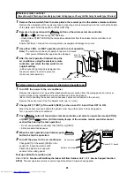
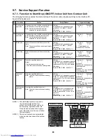
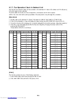
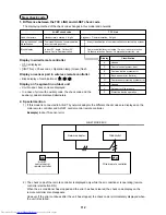
2. Clearing from the interface P.C. board

Using the switches on the interface P.C. board, this function is to clear the currently detected error for each
refrigerant circuit system without resetting the power supply.

(

 Restart of error detection)

Errors in both outdoor and indoor units are once cleared.

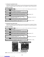
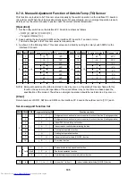
3. Clearing of error check code by power reset

This function is provided to clear error in a refrigerant circuit system by resetting the power of all the outdoor
and the indoor units.

(

 Restart of error detection)

As same as the clearing method on the interface P.C. board, errors of both the outdoor and the indoor units
are once cleared.

Method

Be sure to reset power of both the outdoor and the indoor units.

NOTE) After power reset, it requires usually 3 minutes to power-on due to the initial communication of the

system. In same cases, it requires Max. 10 minutes.

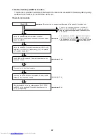
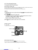
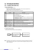
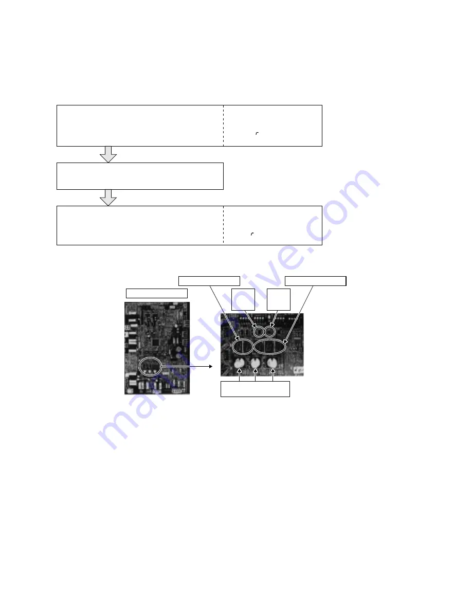
Set the rotary switches on the interface P.C. board of the 
outdoor unit to the following setting.

SW01=[2]  SW02=[16]  SW03=[1]

(7-segment display)

[A]

[   E      ]

[B]

[    C L  ]

Push the push-switch SW04 on the interface P.C. board of 
the outdoor unit for 5 seconds or more. 

[   C L] is displayed in 7-segment display [B] on the P.C. board 
(for 5 seconds), and the error is completely cleared.

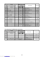
(7-segment display)

[A]

[   E      ]

[B]

[          ]

Interface P.C. board

7-segment display [A]

7-segment display [B]

Push

switch
SW04

Push

switch
SW05

SW01 SW02 SW03

<Rotary switch>

Summary of Contents for MiNi-SMMS MCY-MAP0401HT

Page 1: ...EM AIR CONDITIONER Outdoor Unit Inverter Unit MCY MAP0401HT MCY MAP0501HT MCY MAP0601HT MCY MAP0401HT2D MCY MAP0501HT2D MCY MAP0601HT2D PMV Kit RBM PMV0361E RBM PMV0901E FILE NO A05 015 SERVICE MANUAL PRINTED IN JAPAN Mar 2006 ToMo ...

Page 2: ... the number of high concentration buildings however the installation of multi air conditioner systems is on the increase because of the need for effective use of floor space individual control energy conservation by curtailing heat and carrying power etc Most importantly the multi air conditioner system is able to replenish a large amount of refrigerant compared with conventional individual air co...

Page 3: ...08 SET UP OF THE OUTDOOR UNIT 54 6 CONTROL OUTLINE 55 7 APPLIED CONTROL 63 8 PMV KIT OUT LINE 77 9 TEST OPERATION 79 10 TROUBLESHOOTING 108 11 CONFIGURATION OF CONTROL CIRCUIT 152 12 BACKUP OPERATIONS EMERGENCY OPERATION 166 13 REPLACING COMPRESSOR 167 14 REPLACING PROCEDURE OF PARTS 168 15 P C BOARD 182 16 EXPLODED VIEWS AND PARTS LIST 188 ...

Page 4: ...ory items to do The sentences near an illustrated mark describe the concrete mandatory contents Indicates cautions including danger warning The sentences or illustration near or in an illustrated mark describe the concrete cautious contents Confirmation of warning label on the main unit Confirm that labels are indicated on the specified positions Refer to the Parts disassembly diagram Outdoor unit...

Page 5: ...t than R410A For an air conditioner which uses other refrigerant R22 etc never use R410A If different types of refrigerant are mixed abnormal high pressure generates in the refriger ating cycle and an injury due to breakage may be caused Do not charge refrigerant additionally If charging refrigerant additionally when refrigerant gas leaks the refrigerant composition in the refrigerating cycle chan...

Page 6: ...it even if the refrigerant leaks If the refrigerant leaks and exceeds the limit density an accident of shortage of oxygen is caused For the installation moving reinstallation work follow to the Installation Manual If an incorrect installation is done a trouble of the refrigerating cycle water leak electric shock or fire is caused After repair work has finished check there is no trouble If check is...

Page 7: ...impurities such as water oxide scales oil etc Use the clean pipes Be sure to brazing with flowing nitrogen gas Never use gas other than nitrogen gas 4 For the earth protection use a vacuum pump for air purge 5 R410A refrigerant is azeotropic mixture type refrigerant Therefore use liquid type to charge the refriger ant If using gas for charging composition of the refrigerant changes and then charac...

Page 8: ...Refrigerant charge Refrigerant charge Gas leakage check Refrigerant charge R410A air conditioner installation Existence of new equipment for R410A Yes Yes Yes Yes Yes Yes Yes Yes Note 2 Whether conventional equipment can be used Note 1 Note 1 No No No Yes No No No Conventional air conditioner installation Whether new equipment can be used with conventional refrigerant Yes Note 1 No No Yes Yes No Y...

Page 9: ...uipment Leave it as it is for 1 to 2 minutes and check the indicator of the compound gauge does not return Set the refrigerant cylinder on the electronic balance connect the charge hose to connecting ports of the cylinder and the gauge manifold and then charge the liquid refrigerant from the service port at liquid side Shield with the gauge manifold so that refrigerant does not flow to gas side Co...

Page 10: ...HT2D MCY MAP0601HT2D 12 1 14 0 15 5 12 5 16 0 18 0 6 8 9 1 Rated conditions Cooling Indoor air temperature 27 C DB 19 C WB Outdoor air temperature 35 C DB Heating Indoor air temperature 20 C DB Outdoor air temperature 7 C DB 6 C WB Allocation standard of model name No mark Power supply specification 1Ø 220 230 240V 50Hz 2D Power supply specification 1Ø 220V 60Hz T Inverter unit H Heat pump Develop...

Page 11: ...pe 018 type 007 type 009 type 012 type 015 type 018 type 024 type 027 type 030 type 007 type 009 type 012 type 015 type 018 type 024 type 007 type 009 type 012 type 015 type 018 type 024 type 027 type 030 type 036 type 048 type 007 type 009 type 012 type 015 type 018 type 018 type 024 type 027 type 036 type 048 type 015 type 018 type 024 type 027 type 036 type 048 type Capacity code 1 00 1 25 1 70...

Page 12: ...1 00 1 25 0 80 1 00 1 25 1 70 2 00 2 50 0 80 1 00 1 25 1 70 2 00 2 50 1 70 2 00 2 50 3 00 4 00 5 00 Cooling capacity kW 2 2 2 8 3 6 4 5 5 6 7 1 2 2 2 8 3 6 2 2 2 8 3 6 4 5 5 6 7 1 2 2 2 8 3 6 4 5 5 6 7 1 4 5 5 6 7 1 8 0 11 2 14 0 Heating capacity kW 2 5 3 2 4 0 5 0 6 3 8 0 2 5 3 2 4 0 2 5 3 2 4 0 5 0 6 3 8 0 2 5 3 2 4 0 5 0 6 3 8 0 5 0 6 3 8 0 9 0 10 0 16 0 PMV Kit Available Available Available Av...

Page 13: ...to the capacity code of outdoor unit 1 1 4 PMV Kit Y shape branching joint 4 branching header 8 branching header Model name RBM BY53E RBM BY103E RBM HY1043E RBM HY1083E Usage Indoor unit capacity code 2 Total below 6 4 Indoor unit capacity code 2 Total 6 4 or more and below 7 8 Indoor unit capacity code 2 Total below 7 8 Indoor unit capacity code 2 Total below 7 8 Appearance Model name RBM PMV0361...

Page 14: ...perated from a different location ûC ûF TEST SETTING Wired remote controller Wired remote controller In case of control by 2 remote controllers Simple remote controller Wireless remote controller kit TCB AX21U W E2 RBC AX22CE2 TCB AX21E2 Start Stop Mode change Temperature setting Change of air flow Timer function On or off timer operation setting in 30 minutes increments Automatic Off function Con...

Page 15: ...lectable control modes Central controller mode Remote controller mode Setting of simultaneous ON OFF 3 times for each day of the week combined with a weekly timer Central remote controller ON OFF controller TCB SC642TLE2 TCB CC163TLE2 Connected to outdoor unit or indoor unit Individual control up to 16 indoor units Setting of simultaneous ON OFF 3 times for each day of the week when combined with ...

Page 16: ... PROGRAM DAY button copying of settings easy 4 Two different schedules for a week can be specified Summer schedule and winter schedule etc 5 CANCEL DAY button enables holiday setting 6 If power supply fails the setting contents are stored in the memory for 100 hours WEEKLY TIMER ERROR SuMoTuWeTh Fr Sa PROGRAM1 PROGRAM2 PROGRAM3 Wired remote controller Weekly timer Outdoor unit Central remote contr...

Page 17: ...UNITNo No R C TEST ZONE ALL ZONE GROUP SETTING 1234 SETDATA Name Appearance Model name Wired remote controller RBC AMT31E Simple wired remote controller RBC AS21E2 Weekly timer RBC EXW21E2 Name Appearance Model name Type Wireless remote controller kit RBC AX21U W E2 4 way Air Discharge Cassette type RBC AX22CE2 Under Ceiling type 1 way Air Discharge Cassette type MMU AP 2SH Series TCB AX21E2 Separ...

Page 18: ... 4 5 6 RY302 RY303 1 2 3 1 2 3 1 2 3 1 2 3 1 2 1 2 1 2 3 Fuse T6 3A 250V Fuse T3 15A 250V DC15V DC12V DC7V P301 BLK RED WHI WHI RED S N R L Power supply Single phase 220 240V 50Hz 220V 60Hz Indoor unit Earth screw DM FM Power supply circuit Motor drive circuit Parts name Fan motor Indoor temp sensor Temp sensor Temp sensor Temp sensor Louver motor Drain pump motor Float switch Drain control relay ...

Page 19: ... Power supply Single phase 220 240V 50Hz 220V 60Hz Indoor unit Earth screw Outdoor unit BLU BLU BLK BLK U1 U2 U1 Flow selector unit earth screw Power supply circuit CN01 WHI CN02 YEL Sub P C board MCC 1520 Symbol FM RC TR LM TA TC1 TC2 TCJ RY001 RY002 RY004 RY005 007 FS DM PMV Parts name Fan motor Running capacitor Transformer Louver motor Indoor temp sensor Temp sensor Louver control relay Drain ...

Page 20: ...BLU BLU RED WHI BLK BLK U1 U2 U1 Power supply circuit Network adaptor P C board Symbol FM RC TR LM TA TC1 TCJ RY001 RY002 RY004 RY005 007 FS DM PMV Parts name Fan motor Running capacitor Power transformer Louver motor Indoor temp sensor Temp sensor Louver motor control relay Drain pump control relay Heater control relay Fan motor control relay Float switch Drain pump motor Pulse Motor Valve LM GRN...

Page 21: ...50Hz 220V 60Hz Indoor unit earth screw Closed end connector Flow selector unit earth screw 5 4 1 5 5 5 4 3 3 3 2 1 1 1 CN333 WHI Fuse T3 15A 250V CN82 BLU CN112 WHI CN111 WHI CN110 WHI CN71 CHK High ceiling setup LM CN33 WHI CN334 WHI FM 1 2 3 4 5 6 1 1 1 2 1 2 1 2 1 2 1 2 1 2 2 2 3 3 3 4 4 4 5 3 CN34 RED FS 1 2 3 1 3 4 5 1 2 3 4 5 1 2 3 4 5 1 2 3 4 5 5 5 6 6 6 PMV Motor drive circuit Fuse T6 3A 2...

Page 22: ...5A 250V DC15V DC12V DC7V P301 BLK RED WHI WHI WHI RED Wired remote controller 1 2 B A S N R L U2 1 2 CN1 WHI CN001 WHI Indoor unit power supply Single phase 220 240V 50Hz 220V 60Hz Indoor unit Earth screw Outdoor unit WHI BLK BLK BLU BLU BLK BLK TR WHI U1 U2 U1 DM Power supply circuit Motor drive circuit CN01 WHI CN02 BLU CN03 RED Network adaptor Option 1 2 1 2 1 2 1 2 X Y 3 3 2 2 1 1 Network adap...

Page 23: ...2 3 1 2 3 1 2 3 1 2 1 2 TCJ CN102 RED 1 2 1 2 TA CN104 YEL FS CN030 RED 1 2 1 2 RY001 TR OC EMG RC Fuse T5 0A T10A 250V 1 2 3 1 2 3 CN309 YEL 1 2 3 1 2 3 RED WHI H M L UL 1 indicates the terminal block letter at inside indicates the terminal number 2 A dotted line and broken line indicate the wiring at site 3 indicates the control P C board 4 When attaching a drain pump exchange CN030 connector wi...

Page 24: ...T6 3A 250V Fuse T3 15A DC15V DC12V DC7V P301 BLK RED WHI Closed end terminal RED WHI Wired remote controller Outdoor unit 1 2 B A U2 U1 U2 U1 1 2 CN1 WHI CN001 WHI Indoor unit Earth screw BLK WHI BLK TR BLU WHI BLU BLK BLK DM FM Power supply circuit Motor drive circuit CN01 WHI CN02 BLU CN03 RED Network adaptor Option 1 2 1 2 1 2 1 2 X Y 3 3 2 2 1 1 Network adaptor P C board Color identification R...

Page 25: ... 1 2 3 4 5 6 CN60 WHI 1 2 3 4 5 6 CN61 YEL 1 2 3 1 3 1 3 1 2 1 2 1 2 3 1 3 4 5 CN50 WHI CN41 BLU CN40 BLU GRY BLU BLU BLK BLK BLK WHI GRY CN309 YEL Option 1 2 CN32 WHI Fandrive CN82 BLU Motor drive circuit CN333 WHI CN334 WHI TC1 TC2 CN102 RED TCJ 2 1 2 1 2 1 2 1 2 1 2 1 CN104 YEL TA 1 1 3 3 1 2 3 4 5 6 1 1 1 2 3 4 5 6 1 2 3 4 5 6 1 2 3 4 5 6 2 2 3 4 4 5 5 1 3 5 1 3 1 2 3 1 2 3 5 PMV 1 1 5 4 5 4 L...

Page 26: ...K DC 15V DC 0V DC 12V DC 7V BLK HBS BLK CN22 F S CN82 BLU WHI 1 3 1 3 10 9 8 7 6 5 4 3 2 1 10 9 8 7 4 3 2 1 2 3 4 5 6 7 10 11 1 2 3 4 5 6 1 2 3 4 5 1 2 3 4 5 6 1 2 3 4 5 6 2 3 4 5 6 1 2 3 4 5 6 1 3 4 5 6 1 3 4 5 6 7 8 9 9 5 4 3 2 1 5 4 3 2 1 6 5 4 3 2 1 2 1 6 5 4 3 2 1 3 2 1 4 3 2 1 6 5 4 3 2 1 5 4 3 2 1 2 1 5 4 3 2 1 WHI WHI RED BRW YEL WHI BRW YEL GRY PNK GRY ORN RED BLU Infrared rays receive an...

Page 27: ...J 2 1 2 1 CN101 BLK CN100 BRN 1 3 CN080 GRN TC2 PNL EXCT 2 1 CN073 RED 2 2 1 3 2 4 5 1 Filter CN070 WHI CN081 BLK 2 1 2 1 2 1 1 1 2 2 1 1 2 2 1 1 2 X Y 2 3 2 1 1 3 1 1 2 3 3 1 2 3 4 5 1 2 3 4 5 6 1 2 1 2 3 4 5 6 1 2 3 4 5 6 1 2 3 4 5 6 1 2 3 4 5 6 1 2 3 4 5 6 1 2 3 4 5 6 1 2 3 4 5 6 2 1 TC1 2 1 2 1 CN066 WHI CN067 BLK AC IN RED WHI CN040 BLU Outdoor unit Remote controller Power supply single phase...

Page 28: ...20V 60Hz Indoor unit earth screw Closed end connector CN01 WHI CN03 RED CN02 BLU CN03 RED CN041 BLU CN050 WHI CN061 YEL CN032 WHI Fan drive Option CN060 WHI EMG TR RED RED WHI WHI U1 U2 U1 U2 A B X Y Network adaptor Option Control P C board for undoor unit MCC 1403 MCC 1401 For AP0071BH AP0091BH AP0121BH 1 1 2 2 CN1 1 1 3 3 CN074 WHI CN075 WHI Power supply circuit TR 1 1 3 3 CN068 BLU FAN CN083 WH...

Page 29: ...TCJ 2 1 2 1 CN101 BLK CN100 BRW 1 3 CN080 GRN TC2 PNL EXCT 2 1 CN073 RED 2 2 1 Filter CN070 WHI CN081 BLK 2 1 2 1 2 1 1 1 2 2 1 1 2 2 1 1 2 2 1 1 2 X Y 2 3 2 1 1 3 1 1 2 3 3 1 2 3 4 5 1 2 3 4 5 6 1 2 1 2 3 4 5 6 1 2 3 4 5 6 1 2 3 4 5 6 2 1 4 3 5 2 1 TC1 CN066 WHI AC IN CN044 BRW CN040 BLU Outdoor unit Remote controller Power supply single phase 220 240V 50Hz 220V 60Hz Indoor unit earth screw Close...

Page 30: ... TC1 1 2 3 4 5 CN81 BLK 1 2 3 4 5 CN50 WHI CN309 YEL 1 2 3 4 5 CN60 WHI CN32 WHI Option 1 2 Fan drive 1 2 3 4 5 6 CN61 YEL CN41 BLU CN40 BLU CN44 BRW 1 2 3 4 5 6 1 1 2 2 1 1 2 3 3 BLU BLU BLK BLK 3 1 3 1 3 1 3 1 3 1 3 1 2 1 CN66 WHI WHI RED P301 CN67 BLK Motor drive circuit CN304 GRY RY302 CN68 BLU CN68 BLU Fuse T6 3A 250V Drain pump type SPH Type Non Drain pump type SH Type BLK RED WHI 2 1 Fuse T...

Page 31: ...31 Capacitor 2 2 Outdoor Unit Model MCY MAP0401HT MCY MAP0501HT MCY MAP0601HT MCY MAP0401HT2D MCY MAP0501HT2D MCY MAP0601HT2D ...

Page 32: ...nection of PMV Kit Model RBM PMV0361E RBM PMV0901E PMV PMV Kit Indoor unit CN82 connector Connector conversion cable Indoor control P C board Connection cable PMV lead wires Pulse motor valve PMV Indoor unit side ...

Page 33: ...t switch FS 0218 102 TA sensor Lead wire length 155mm TC1 sensor Ø4 size lead wire length 1200mm Vinyl tube Blue TC2 sensor Ø6 size lead wire length 1200mm Vinyl tube Black TCJ sensor Ø6 size lead wire length 1200mm Vinyl tube Red Pulse motor EDM MD12TF 3 Pulse motor valve EDM B60YGTF 1 Louver motor panel MP24GA Compact 4 way Air Discharge Cassette Type Model MMU AP 0071MH 0091MH 0121MH 0151MH 018...

Page 34: ...Ø4 size lead wire length 1200mm Vinyl tube Blue TC2 sensor Ø6 size lead wire length 1200mm Vinyl tube Black TCJ sensor Ø6 size lead wire length 1200mm Vinyl tube Red 1 way Air Discharge Cassette Compact type Type Model MMU AP 0071YH 0091YH 0121YH Fan motor AF 200 22 4N 1 Running capacitor for fan motor AC 400V 1µF Drain pump motor PJD 05230TF 1 Float switch FS 0208 602 Control P C board transforme...

Page 35: ... Vinyl tube Red Concealed Duct High Static Pressure Type Model MMD AP 0181H 0241H 0271H 0361H 0481H Fan motor STF 200 160 4B STF 200 160 4A STF 200 260 4C STF 200 260 4B Running capacitor for fan motor AC 500V 4µF AC 400V 8µF AC 450V 6µF AC 400V 8µF Drain pump motor ADP 1409 Float switch FS 0218 102 6 Pulse motor EDM MD12TF 3 Pulse motor valve EDM B40YGTF EDM B60YGTF 1 TA sensor Lead wire length 1...

Page 36: ...Running capacitor for fan motor AC450V 1 2µF AC400V 1 8µF AC450V 2µF Transformer TT13 Pulse motor EDM MD12TF 3 Pulse motor valve EDM B25YGTF EDM B40YGTF TA sensor Lead wire length 818mm Vinyl tube TC1 sensor Ø4 size lead wire length 1200mm Vinyl tube Blue TC2 sensor Ø6 size lead wire length 1200mm Vinyl tube Black TCJ sensor Ø6 size lead wire length 1200mm Vinyl tube Red Floor Standing Concealed T...

Page 37: ... Accumulator AC240V 24W Compressor case thermo US 622KXTMQO SS OFF 125 C ON 90 C Model MCY MAP0401HT2D MCY MAP0501HT2D MCY MAP0601HT2D Compressor DA421A3F 20M2 4 way valve coil VHV type AC220V 60Hz 4 way valve STF 0401G1 Pulse motor valve coil HAM MD12TF 3 DC12V Pulse motor valve HAM BD24TF 1 Solenoid valve coil SV2 SV4 SV5 VPV type AC220V 60Hz Solenoid valve SV2 VPV122DQ1 SV4 SV5 VPV303DQ1 High p...

Page 38: ...alve Low pressure sensor Solenoid valve SV5 Liquid tank 4 way valve Solenoid valve SV2 High pressure sensor Solenoid valve SV4 TD sensor High pressure switch Compressor Compressor case heater TO sensor Accumulator Accumulator heater TE sensor 3 5 Parts Layout in Outdoor Unit 38 ...

Page 39: ... TIMER SET CODENo UNIT No TEST SETTING DATA SET R C No H C TEST SETTING 3 6 Name of Each Part 3 6 1 Outdoor Unit Wired remote controller RBC AMT31E Simple wired remote controller RBC AS21E2 Wireless remote controller kit TCB AX21E2 RBC AX22CE2 RBC AX21U W E2 WEEKLY TIMER ERROR SuMoTuWeTh Fr Sa PROGRAM1 PROGRAM2 PROGRAM3 SELECT ZONE CL SET GROUP CODE No UNITNo No R C TEST ZONE ALL ZONE GROUP SETTIN...

Page 40: ...r Display section In the display example all indicators are displayed for the explanation In reality only the selected contents are displayed When turning on the leak breaker for the first time SET DATA flashes on the display part of the remote controller While this display is flashing the model is being automatically confirmed After the SET DATA display has disappeared you may use the remote cont...

Page 41: ...controls the multiple indoor units the setup operation is unavailable in group control 1 3 2 4 ON OFF FAN TEMP SWING FIX TIME MODE VENT UNIT SET CL FILTER RESET TEST TIMER SET HEAT DRY COOL FAN Heat pump model DRY COOL FAN Cooling only model Dehumidity LOW MED HIGH AUTO 3 8 Correct Usage When you use the air conditioner for the first time or when you change the SET DATA value follow the proce dure...

Page 42: ...is ready to begin the heat ing operation In Cooling operation Use the discharge flap with a horizontal set point In Heating operation For Heat pump model only Use the discharge flap with a downwards set point ON OFF FAN TEMP SWING FIX TIME MODE VENT UNIT SET CL FILTER RESET TEST TIMER SET In FAN operation 1 2 3 4 In all modes Display when stopping the swing Initial setup Series of operation Fan He...

Page 43: ...red direction Setup the air flow direction and swinging function Refer to the description of the 2 way Air Discharge Cassette Type Initial setup Initial setup ON OFF FAN TEMP SWING FIX TIME MODE VENT UNIT SET CL FILTER RESET TEST TIMER SET In FAN operation 1 2 3 4 In all modes Display when stopping the swing Initial setup Series of operation Fan Heat operation Cool Dry operation Unit No 1 1 No dis...

Page 44: ...rizontal flap using the SWING FIX button on the remote controller The horizontal flap will not stop immediately even if the switch is pushed Note Pushing the switch again when the required louver direc tion has been reached will stop the louver Adjustment of air flow direction rightwards leftwards To change the air outlet direction to the right or left side set the vertical flap located behind the...

Page 45: ...d air outlet dew may form on the surface of the cabinet or the horizontal flap resulting in possible dripping of water If heating operation is performed with the horizontal air outlet actively moving unevenness of the tem perature may increase in the room Do not move the flap directly with your hands during swing operation otherwise a fault may be caused The vertical flap does not stop immediately...

Page 46: ... correct capacity fuses are used Using wire or copper wire may cause a fire or unit fault Ensure that the power supply to the unit is exclusive and is the correct rated voltage To disconnect the appliance from the main power supply This appliance must be connected to the main power supply by means a circuit breaker or a switch with a contact separation of at least 3mm 4 way Air Discharge Cassette ...

Page 47: ...s of the filter are positioned correctly inside of the plastic frame Close the air inlet grille If the FILTER lamp on the indoor unit is displayed press the FILTER button on the remote controller or the TEMPORARY button on the indoor unit This will turn the light off Cleaning the air inlet grille 1 Remove the air inlet grille Hold the two sides of the air inlet grille and open upwards Move the cen...

Page 48: ...ted after being stop or the power supply has been turned on This is to protect the system Main power failure If a power failure occurs during operation all operations stop When restarting the unit push the ON OFF button again Fan rotation of stopped unit When other indoor units within the same system are in operation the fan on the indoor units that are on stand by will rotate to protect the machi...

Page 49: ...heard A stopping indoor unit in the same operating air conditioner system emitted sound white vapor or cool air Slight Pishi sound is heard Discharge air smells indication is lit When power of the air conditioner is turned on Ticktock sound is heard Operates or stops automatically Does not operate Air is not cooled or warmed sufficiently Cause Fan of the outdoor unit stops automatically and perfor...

Page 50: ...hen pushing the SET and TEST buttons at the same time for 4 seconds or more the following display will appear If Service check is displayed the mode enters into the error history mode 01 Order of error history is displayed in CODE No window Check code is displayed in CHECK window Indoor unit address in which the error has occurred is displayed in UNIT No For every push of the button the error hist...

Page 51: ... joint Check joint Check joint High pressure switch High pressure sensor Low pressure sensor Capillary tube 1 Capillary tube 2 Sensor TD Sensor TS Muffler Liquid tank Strainer Liquid side packed valve Gas side ball valve Check valve 4 way valve Compressor Inverter Accumulator Sensor TL Sensor TE Sensor TO Solenoid valve SV2 Solenoid valve SV5 Heat exchanger Strainer PMV Strainer Outdoor unit ...

Page 52: ...eating operation 2 Sub cool adjustment function in cooling operation 1 Protection of compressor discharge temp Used for release 1 Controls super heat in heating operation 1 Controls defrost in heating operation 2 Controls outdoor fan in heating operation 1 Detects under cool in cooling operation 1 Detects outside temperature 1 Detects high pressure and controls compressor capacity 2 Detects high p...

Page 53: ... indoor suction temperature Connector CN100 3P Brown 1 Controls PMV super heat in cooling operation Connector CN101 2P Black 1 Controls PMV under cool in heating operation Connector CN102 2P Red 1 Controls PMV super heat in cooling operation 2 MMU AP0071 to AP0121YH only Controls PMV under cool in heating operation Air heat exchanger at indoor side Fan M Fan motor Sensor TA Sensor TC1 Gas side Liq...

Page 54: ...g PMV Kit in the Mini SMMS system 2 When using the indoor unit under high humidity condition Reference Indoor side 27 C dry bulb temperature 24 C wet bulb temperature Operation time 4 hours or more 5 1 Setup Method Turn on DIP switch SW08 on the interface P C board of the outdoor unit SW11 1 ON 2 3 4 SW12 1 ON 2 3 4 SW06 1 ON 2 3 4 SW07 1 ON ON ON ON 2 3 4 SW09 SW08 1 1 2 3 4 SW10 1 2 3 4 SW13 1 O...

Page 55: ...eration Cooling operation Dry operation Heating operation 1 Set point temperature adjustment range on remote controller C Wired type Wireless type All cooling 18 to 29 C 18 to 30 C All heating 18 to 29 C 16 to 30 C 2 The set point temperature in heating operation can be offset using item code DN 06 Setup data Setup temp correction 0 2 4 6 0 C 2 C 4 C 6 C Setup at shipment Setup data 2 1 The differ...

Page 56: ...When 1 zone is detected the timer is cleared and the operation returns to the normal operation When the command frequency became S0 with continua tion of J zone operation of the the indoor fan in LOW mode until it reaches the 1 zone It is reset when the following conditions are satisfied Reset conditions 1 TC1 12 C and TC2 12 C and TCJ 12 C 2 30 minutes passed after stop 2 In all cooling operation...

Page 57: ...ff by changing the set up temp the thermostat is OFF with even the above condition The protective control has priority 1 During COOL operation including DRY operation the drain pump operates 2 While the drain pump operates if the float switch works the drain pump continues operation and a check code is displayed 3 While the drain pump stops if the float switch works turn off the capacity demand co...

Page 58: ...tion the fan rotates with lower air speed than one specified in order to prevent discharge of cold draft or stops including case that defrost operation is being performed HEAT operation cannot be performed because COOL priority is set Outdoor I F P C board SW11 bit 1 is ON and the other indoor unit is under COOL DRY operation 2 HEAT standby is displayed until the above conditions are released 1 Th...

Page 59: ...rged 3 Fan control for mainly cooling part heating operation The outdoor fan speed mode is controlled according to the target of the Pd Discharge pressure Remarks When TE temp ambient temperature exceeds 25 C Heating operation stops The maximum fan speed differs depend ing on the outdoor HP 3 Capacity control Min frequency 26Hz 1 The capacity request command received from the indoor controller det...

Page 60: ...the inverter 3 SV2 low pressure release control This control is to prevent quick pressure dropping transient operation This control is individually executed by the header outdoor unit This control is executed as necessary except during stop time and thermostat OFF time 4 SV4 low pressure release control This control is to prevent low pressure dropping and is individually executed by the header uni...

Page 61: ...ase control Feedback from the AC input current sensor CT is used to prevent the inverter input current exceeding its specified limit 2 Heat sink temperature detection control Feedback from the thermistor TH on the compressor driving module is used to prevent the IGBT from overheating The highest value is taken from IPDU TH sensors 3 Over current protective control When an over current condition is...

Page 62: ... for outdoor unit 1 When the system power is turned on an audible clicking sound is omitted due to the PMV initializing this is a normal condition When the outdoor unit is situated near other sources of noise this sound may not be noticeable 2 Do not remove the driving part head of the PMV during operation as it may cause the PMV to malfunction 3 When transporting or replacing the outdoor unit nev...

Page 63: ...umbers in the group control are successively displayed In this time the fan of the selected indoor unit only is turned on 3 Specify the item code DN using the setup temperature and buttons 4 Select the setup data using the timer time and buttons When selecting the DN code to 33 change the temperature indication of the unit from C to F on the remote controller 5 Push SET button OK if display goes o...

Page 64: ... Air Discharge Cassette type and Under Ceiling type 0000 0 deg to 0010 10 deg For setup temperature reversal of COOL HEAT by Data value 2 0000 None 0001 Restart 0000 Usual 0001 Condition ignored Detection control for heat exchanger temperature 0000 Filter input 0001 Alarm input Air washer etc 0002 None 0000 Usual 0001 Leaving ON prevention control 0000 Unavailable 0001 Available 0000 Unavailable 0...

Page 65: ... Floor Standing Concealed Floor Standing Compact 4 way Air Discharge Cassette Abbreviated Model name MMU AP SH MMU AP H MMU AP WH MMU AP YH MMD AP BH MMD AP SPH SH MMD AP H MMC AP H MMK AP H MML AP H MML AP BH MMF AP H MMU AP MH Setup data 0001 0003 0005 0007 0009 0011 0012 0013 0015 0017 0018 0021 0023 Model 007 009 012 015 018 024 027 030 036 048 056 072 096 Setup data 0000 0001 0002 0003 0004 0...

Page 66: ... signal Output during normal operation 3 Error signal Output during alarm Serial communication error or indoor outdoor protective device operation 2 Wiring diagram using remote control interface TCB IFCB 4E Input IFCB 4E No voltage ON OFF serial signal Output No voltage contact for operation error display Contact capacity Below Max AC240V 0 5A 1 2 3 4 5 6 CN61 T10 YEL 1 2 3 4 1 2 3 4 5 6 CN13 CN06...

Page 67: ...the indoor unit numbers in group control are displayed succes sively In this time the fan of the selected indoor unit only turns on 3 Using the setup temp or button specify the item code 4 Using the timer time or button select the setup data At shipment The setup data are as follows Setup data Handling of operation of air to air heat exchanger or ventilating fan Unavailable At shipment Available 1...

Page 68: ...at card is taken out from the card switch box When the card switch box does not perform the above contact operation convert it using a relay with b contact 2 Operation Handle the wired remote controller switch in the following procedure Use the wired remote controller switch during stop of the system 1 Push concurrently SET CL TEST buttons for 4 seconds or more 2 Using the setup temp or button spe...

Page 69: ... For power peak cut control expansion selection CN511 Green CN508 Red CN513 Blue CN510 White Connector position detail Switch position detail No 1 2 3 4 5 Function Power peak cut control Standard Power peak cut control Expansion External master ON OFF control Night operation control Operation mode selection control Switch No SW07 SW07 Bit 1 1 2 Connector No CN513 CN513 CN512 CN508 CN510 Used contr...

Page 70: ... place the support of the electric component box Fig 1 Optional P C board CC Up to a total of two boards TCB PCDM2E left side TCB PCIN2E both side TCB PCMO2E right side Interface P C board Hook part Screw Screw Electric component box Wire clamp accessory Output wiring Electric component box Grounding screw is accessory Fig 2 Fig 4 Fig 3 7 2 3 Wiring 1 Refer to the Electric wiring diagram when wiri...

Page 71: ...Normal 100 Normal Up to 60 Up to 80 Display relay L1 OFF ON CAUTION Be sure to prepare non voltage point for each terminal Display relay capacity of OPERATION Below AC240V 0 5A COSf 100 When connecting load such as relay coil to L1 load insert the noise surge absorber Below DC24V 1A Non inductive load When connecting load such as relay coil to L1 load insert the bypass circuit In case of pulse sig...

Page 72: ...to L1 load insert the bypass circuit Input SW 1 SW 2 OFF OFF ON OFF OFF ON ON ON SW07 Bit 1 OFF Capacity Current 100 Normal 100 Normal Up to 80 Up to 80 Up to 60 Up to 70 0 Stop 0 Stop SW07 Bit 1 ON Capacity Current 100 Normal 100 Normal Up to 85 Up to 90 Up to 75 Up to 80 Up to 60 Up to 70 Display relay L1 OFF ON ON ON L1 Display lamp surging power peak cut control Connection cable SW07 Bit 2 ON ...

Page 73: ...gram SMC Input signal for start SMH Input signal for stop Connection cable Outdoor unit Local supply I F P C board TCB PCMO2E HEAT COOL COM SMC Shield CN512 PJ17 SMH CAUTION Be sure to prepare non voltage pulse point of contact for each terminal This control is conducted when input signal stand up or fall down Standing and falling status should be held for 100 m sec or more Input wiring Size 3 cor...

Page 74: ...AUTION Be sure to prepare non voltage continua tion point of contact for each terminal Reference 1 This sound pressure level are measured in an anechoic chamber in accordance Location of microphone The front of 1 m a height of 1 5 m Cooling Outdoor temperature 25 C DB Heating Outdoor temperature 7 C DB 6 C WB 2 Against Max capacity Cooling Outdoor temperature 25 C DB Heating Outdoor temperature 7 ...

Page 75: ...L SMC HEAT SMH ON OFF OFF ON OFF OFF Selected operation mode Only cooling mode permitted Only heating mode permitted Normal operation Note 1 1 1 mode select control mark is indicated on the remote controller display CAUTION Be sure to prepare non voltage continuous point of contact for each terminal Connection cable Outdoor unit Local supply I F P C board TCB PCMO2E HEAT COOL COM SMC Shield CN510 ...

Page 76: ...coil to L1 L2 load insert the noise surge absorber Below DC24V 1A Non inductive load When connecting load such as relay coil to L1 L2 load insert the bypass circuit L1 Operation monitoring lamp Connection cable Outdoor unit Local supply I F P C board TCB PCIN2E Display relay OPERATION L2 Error monitoring lamp L1 Power supply Display relay L2 Power supply Shield wire CN513 PJ17 EMG In conformity wi...

Page 77: ...V of PMV Kit and PMV in indoor unit does not be used After that refrigerant noise of PMV will be coming from back ceiling board and refrigerant noise of indoor unit may be restrained Image of installation Without PMV Kit With PMV Kit 8 2 How to Use Connect PMV Kit between refrigerant pipe of indoor unit Connect control cable of PMV Kit to control P C board of indoor unit then PMV Kit is controlled...

Page 78: ... outdoor units operation and turn off power supply to each units 2 Remove connection cable of PMV Kit from P C board of indoor unit and connect PMV of indoor unit to P C board MMK APXXX2H High Wall Type does not use a this conversion cable 3 Turn on power supply of only indoor unit and fully open PMV of indoor unit Note While turn on power supply of indoor unit outdoor unit also turns on power sup...

Page 79: ...3 U4 terminal removed Set up at shipment from the factory Is the terminator resistor SW30 2 on the interface P C board of the outdoor unit turned on Set up at shipment from the factory Is the end terminal of the shield cable grounded Check Outdoor unit U1 U2 U3 U4 E N L 3 A B U1 U2 E N L 2 4 1 A B U1 U2 E N L Indoor unit Earth leakage breaker Power supply Power supply Over current breaker fuse Ear...

Page 80: ...onal gas has been charged Are valves of all the outdoor units fully opened Gas side Liquid side outdoor unit A XXXX XXXX Check list 2 Calculate the additional amount of refrigerant from the following Pipe dia at liquid side Ø6 4 Ø9 5 Standard amount of refrigerant kg m 0 025 0 055 Total pipe length at each liquid side Additional amount of refrigerant by pipe length A Additional amount of refrigera...

Page 81: ...02 SW03 7 segment display B 9 4 Address Setup After power ON set up the indoor address from the interface P C board of the outdoor unit The address setup operation cannot be performed by power ON only 9 4 1 Cautions 1 It requires approx 5 minutes usually for 1 line to automatically set up address However in some cases it may require maximum 10 minutes 2 It is unnecessary to operate the air conditi...

Page 82: ...emote controller Central remote controller Outdoor Indoor Indoor Remote controller Central remote controller Outdoor Indoor Indoor Remote controller Remote controller Outdoor Indoor Indoor Remote controller Central remote controller REQUIREMENT When a group control is performed over the multiple refrigerant lines be sure to turn on the power supplies of all the indoor units connected in a group at...

Page 83: ...roller U1 U2 A B U3 U4 U1 U2 U5 U6 U1 U2 A B Remote controller Relay connector Relay connector ON 1 2 1 2 3 3 1 Outdoor unit Outdoor unit Outdoor unit ON Open OFF after address setup OFF after address setup Outdoor interface P C board 2 1 SW30 ON OFF SW30 2 1 SW30 ON OFF 2 1 ON OFF Manual address setup from remote controller In case to decide an address of the indoor unit prior to finish of indoor...

Page 84: ... the same refrigerant line can be confirmed An outdoor unit is selected the indoor unit numbers in the same refrigerant line are successively displayed and then its indoor unit fan is turned on 1 Push the timer time TEST buttons simultaneously for 4 seconds or more Firstly the line 1 item code Address Change is displayed Select outdoor unit 2 Using UNIT SWING FIX buttons select the line address 3 ...

Page 85: ...rom a wired remote controller 0099 is set up to line address indoor address and group address data from the remote controller For the setup procedure refer to the abovementioned address setup from the remote controller Method 2 Clear the indoor addresses in the same refrigerant line from the outdoor unit 1 Turn off the power of the refrigerant line to be returned to the status at shipment and chan...

Page 86: ...of the outdoor unit SW01 SW02 SW03 2 14 2 SW04 After checking that is displayed on 7 segment display and then push SW04 for 5 seconds or more U3 U4 U1 U2 U1 U2 A B Outdoor unit Remote controller U1 U2 A B Remote controller U3 U4 U1 U2 U1 U2 A B Remote controller U1 U2 A B U3 U4 U1 U2 U1 U3 U2 U4 U5 U6 U1 U2 A B Remote controller Outdoor unit Outdoor unit Central control device Added indoor unit 9 ...

Page 87: ...ndition that a normal operation can be performed Exceeded No of connected indoor units or exceeded capacity Duplication of outdoor addresses Only when outdoor address was manually set up Duplication of outdoor line addresses Line address setup error occurred after connec tion between U1 U2 and U3 U4 connectors Duplicated of indoor units with priority There are two or more indoor units set up with ...

Page 88: ... follower unit in the individual control Unit which does not response to remote controller The power is not turned on Unit which is not displayed on remote controller Remote controller is not connected with cable Unit which is not displayed on remote controller Miscabling of remote controller Unit which is not displayed on remote controller Remote controller communication circuit error Unit which ...

Page 89: ... Indoorunit A B Indoorunit Outdoor unit U1 U2 Indoorunit Indoorunit Incorrect wiring example Fig 1 Remote controller status No response Header unit 7 segment display E19 00 Incorrect example Fig 2 Status Number of connected outdoor units is short Incorrect example ...

Page 90: ...roller and outdoor interface P C board 1 Test operation start stop operation Test operation from remote controller Wired remote controller 1 When pushing TEST button for 4 seconds or more TEST is displayed in the display section and the mode enters the test operation mode 2 4 3 1 5 ON OFF FAN TEMP SWING FIX TIME MODE VENT UNIT SET CL FILTER RESET TEST TIMER SET TEST TEST 2 Push ON OFF button 3 Usi...

Page 91: ...e the adjust corner cap and the attached with sensor section from the ceiling panel For removal method follow to the installation instructions attached to the ceiling panel Be careful to handling the sensor section because cables are connected to the sensor Remove the sensor cover from the adjust corner cap 1 screw 2 Change Bit 1 TEST of the switch S003 on the sensor P C board from OFF to ON Mount...

Page 92: ...utton After checking the receiving sound Pi immediately After checking the receiving sound Pi immediately push Temperature set button to set to 19 C push Temperature set button to set to 29 C After checking the receiving sound Pi immediately After checking the receiving sound Pi immediately push Temperature set button to set to 18 C push Temperature set button to set to 30 C Then repeat the proced...

Page 93: ...eck operation status of the compressor Is air circulation good Is the operating current normal Is the operating pressure normal Check direction of the louver Execute a test operation using Function of start stop the indoor unit from outdoor unit in Service support function Check power voltage of the main power supply Check cable size of the power supply Check temperature load of the indoor room ou...

Page 94: ... length combination of indoor units or connected indoor capacity For a compressor the left side is 1 and the right side is 2 viewed front the front of the unit Even if two compressors operate the frequency difference may set as a measures against resonance The temperature of indoor heat exchanger TC indicates TCJ sensor temperature in cooling time and TC2 sensor temperature in heating time respect...

Page 95: ...atus Stops the specified indoor unit Note The other indoor units keep existing status Operates the specified indoor unit Note The other indoor units keep existing status Setup Release Setup Push SW04 for 2 seconds or more with SW01 2 SW02 5 SW03 1 Release Return SW01 SW02 SW03 to 1 Setup Push SW04 for 2 seconds or more with SW01 2 SW02 6 SW03 1 Release Return SW01 SW02 SW03 to 1 Setup Push SW04 fo...

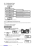
Page 96: ...ion check Stop End Interface P C board 7 segment display A 7 segment display B SW04 SW05 SW01 SW02 SW03 Rotary switch 2 Heating test operation function This function is provided to change collectively the mode of all the indoor units connected to the same system for heating test operation mode using switches on the interface P C board of the outdoor unit Operation procedure NOTE The test operation...

Page 97: ...e operation continues in the current mode FAN COOL HEAT Set on the interface P C board of the outdoor unit SW01 to 2 Sw02 to 7 and SW03 to 1 respectively CH is displayed on 7 segment display A Push SW04 on the interface P C board of the outdoor unit for 2 seconds or more The indoor unit to be started operates After test operation return the rotary switches SW01 SW02 and SW03 on the interface P C b...

Page 98: ... the interface P C board of the header unit for 2 seconds or more If pushing this switch continuously for 10 seconds or more the operation changes to the individual test operation The indoor unit to be started operates Push the push switch SW05 on the interface P C board of the outdoor unit for 2 seconds or more 7 segment display A Address display of corresponding indoor unit B 00 is displayed for...

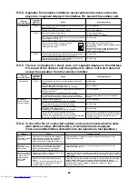
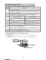
Page 99: ...nds or more 2 Using buttons set FF to item code The display in Section A in the following figure is counted with interval of 5 seconds as When the count arrives the error is cleared However counting from is repeated on the display 3 When TEST button is pushed the status returns to the normal status Error clearing in indoor unit Error in the indoor unit is cleared by ON OFF button on the remote con...

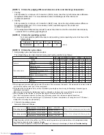
Page 100: ...of both the outdoor and the indoor units are once cleared Method Be sure to reset power of both the outdoor and the indoor units NOTE After power reset it requires usually 3 minutes to power on due to the initial communication of the system In same cases it requires Max 10 minutes Set the rotary switches on the interface P C board of the outdoor unit to the following setting SW01 2 SW02 16 SW03 1 ...

Page 101: ... P C board of the outdoor unit as follows SW01 2 SW02 4 SW03 1 7 segment display A A 1 B 7 segment display A A 1 A FF Push the push switch SW04 on the interface P C board of the outdoor unit for 2 seconds or more display of the connected remote controller flashes Push the push switch SW05 on the interface P C board of the outdoor unit for 2 seconds or more Operation Check the connected remote cont...

Page 102: ...terface P C board of the outdoor unit SW01 to 2 SW02 to 3 SW03 to 1 and push SW05 for 2 seconds or more Display shown on 7 segment display for one minute as follows P 00 Clear After 2 minutes 1 minutes for Close fully have passed when setup has finished the PMV automatically returns to the normal operation 9 7 5 Pulse Motor Valve PMV Forced Open Fully Close fully Function in Outdoor Unit This func...

Page 103: ...elow ON OFF output pattern of each solenoid valve is as below NOTE 1 Be aware that there is a 5 second delay in the operation of the selected solenoid valve after SW02 has been set NOTE 2 The mark in the table indicates the selected solenoid valve is forced on NOTE 3 The mark in the table indicates the selected solenoid mode will depend on the specifications of the air conditioner NOTE 4 The mark ...

Page 104: ...3 From when fan step 31 is displayed in 7 segment display B the fan starts operation Max step operation 4 After then 7 segment display B and the fan step are changed by changing the setup number of the switches SW02 and SW03 Output pattern of the fan is as follows Clear This function is cleared by one of the following operations 1 When SW01 setting number was changed to other number 2 Push switch ...

Page 105: ...r 1 second or more The mode changes to the TO sensor value fix manual mode 3 As shown in the following table TO sensor value can be fixed by setting the rotary switch SW02 on the interface P C board SW01 SW02 SW03 7 segment display B TO sensor value SW01 SW02 SW03 7 segment display B TO sensor value 1 10 10 C 9 45 45 C 2 15 15 C 10 15 15 C 3 20 20 C 11 10 10 C 4 25 25 C 12 5 5 C 5 30 30 C 13 0 0 C...

Page 106: ...ning again Clear Open CHK pin If the system is operating it stops once but automatically restart after several minutes For the details of CHK pin CN71 on indoor P C board and DISP pin CN72 on indoor P C board refer to 11 Control circuit configuration Indoor unit 2 Indoor P C board MCC 1402 and MCC 1403 9 7 10 Indoor Fan Only Operating Mode When operating an air conditioner with indoor units and re...

Page 107: ...r suction temp TA Indoor coil temp TCJ Indoor coil temp TC2 Indoor coil temp TC1 Indoor discharge temp Tf NOTE 1 Indoor PMV opening No of connected indoor units Total HP of connected indoor units No of connected indoor units Total HP of outdoor units Unit C C C C C C C pulse unit HP unit HP Display format 1 1 1 1 1 1 10 10 10 NOTE 1 Only a part of indoor unit types is installed with the discharge ...

Page 108: ...mer Is the system initially communicating Heating operation cannot be performed under the condition that the outside temperature is 21 C or higher Cooling operation cannot be performed under the condition that the outside temperature is 5 C or lower Is cold draft prevention control operating at heating mode Is it in low ambient cooling control Is a defrost operation being performed Is the fan oper...

Page 109: ...7 99 l l Communication error between indoor units Indoor E19 E19 00 Header is nothing 02 Two or more header units 96 l l Outdoor header units quantity error I F E20 E20 01 Outdoor of other line connected 02 Indoor of other line connected 42 l l Other line connected during automatic address I F E23 E23 15 l l Sending error in communication between outdoor units I F E25 E25 15 l l Duplicated followe...

Page 110: ...omp 1 17 l l Current detect circuit system error IPDU H04 H04 44 l l Comp 1 case thermo operation I F H06 H06 20 l l Low pressure protective operation I F L03 96 l SIM Indoor center unit duplicated Indoor L04 L04 96 SIM Outdoor line address duplicated I F L05 96 l SIM Duplicated indoor units with priority Displayed in indoor unit with priority I F L06 L06 No of indoor units with priority 96 l SIM ...

Page 111: ... Fan motor current error d Fan motor lock 1A l ALT Outdoor fan IPDU error Fan IPDU P26 P26 01 Comp 1 side 02 Comp 2 side 14 l ALT G TR short protection error IPDU P29 P29 01 Comp 1 side 02 Comp 2 side 16 l ALT Comp position detective circuit system error IPDU P31 47 l ALT Other indoor unit error Group terminal unit error Indoor b7 By alarm device ALT Error in indoor group AI NET 97 AI NET communic...

Page 112: ...a case of error with auxiliary code the check code and the auxiliary code are displayed alternately Display A C E F H J L P Classification Unused Central control system error Communication system error Each sensor error Failure Compressor protective system error Unused Setup error Other errors Protective device operation 2 Special mention 1 If this model is connected to AI NET by network adaptor t...

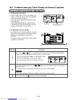
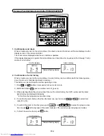
Page 113: ... the memory are displayed in order The numbers in item code indicates item code 01 most recent to 04 Oldest CAUTION If CL button is pushed all of the error histories of the indoor unit will be deleted After confirmation push TEST button to return to the usual display CODENo UNIT No R C No 1 Confirmation and check When a trouble occurs in the air conditioner the check code and the indoor unit No ar...

Page 114: ...the error history can be confirmed with the following proce dure Up to 4 error histories are stored in memory This history can be confirmed from either operating or stop 1 Push and SET buttons in succession for 4 seconds or more 2 SERVICE CHECK goes on and Item code 01 goes on 3 When selecting flash the group number if there is the alarm history the UNIT number and the latest alarm history are dis...

Page 115: ...p sensor is defective For No 16 unit the high pressure switch at the inverter unit side operates Example There is no check data Unit line No Network address No Check code detected at first Check code detected at last FILTERRESET 49505152535455565758596061626364 33343536373839404142434445464748 171819 20212223242526272829303132 1 MONITOR SET ZONE ALL CENTER LOCKED AUX TYPE TIMER No STANDBY FILTER O...

Page 116: ...heck power ON order of indoor outdoor Check indoor address setup Check inter unit cabling between indoor and outdoor Check outdoor end terminal resistance setup SW30 2 E06 E06 No of indoor units which received signal normally 4 I F Decreased number of indoor units All stop When signal is not sent for a certain period from the indoor unit which has been used to send signals E06 is normally displaye...

Page 117: ...s Corresponding unit only stops Regular communication between indoor header and follower units Check cable of the remote controller Check power cabling of indoor Check P C board of indoor E19 E19 00 No header unit 02 Two or more header units 96 I F Outdoor unit quantity error All stop There are multiple outdoor units in 1 line There is none of outdoor unit in 1 line The outdoor unit connected with...

Page 118: ...rt Check connection of TL sensor connector Check characteristics of TL sensor resistance value Check outdoor P C board I F error F08 F08 1b I F TO sensor error All stop Resistance value of sensor is infinite or zero Open Short Check connection of TO sensor connector Check characteristics of TO sensor resistance value Check outdoor P C board I F error F10 OC Indoor Indoor TA sensor error Correspond...

Page 119: ...Compressor 1 1F IPDU Compressor breakdown All stop Inverter current detection circuit detected over current and stopped Check power voltage AC220 240V 10 Check compressor error Check cause of abnormal overload operation Check outdoor P C board IPDU error H02 H02 01 Compressor 1 1d IPDU Compressor error lock All stop Over current was detected several seconds after header compressor had started Chec...

Page 120: ...icated Check display of indoor unit with priority L06 L06 No of indoor units with priority 96 I F Duplicated indoor units with priority Displayed on the unit other than indoor unit with priority All stop Indoor units with priority were duplicated Check display of indoor unit with priority and outdoor unit L07 99 Indoor Group line in individual indoor unit Corresponding unit only stops At least one...

Page 121: ...only stops Check the lock of fan motor AC fan Check cabling P03 P03 1E I F Discharge temp TD1 error All stop Discharge temp TD1 exceeded 115 C Check full opening of outdoor service valves Gas side Liquid side Check clogging of outdoor PMV Check characteristics of TD1 sensor resistance value Check refrigerant shortage Check 4 way valve error Check leakage of SV4 circuit Check SV4 circuit Miswiring ...

Page 122: ...ating While the system is operating in HEAT mode outdoor PMV of which opening degree was 100 pulse or less for a certain time Check full close operation of outdoor PMV Check Pd and Ps sensor error Check clogging of SV2 circuit Check clogging of 4 way valve error circuit Check outdoor P C board I F error Check capillary clogging of oil return circuit from oil separator Check TS sensor error P15 P15...

Page 123: ...of discharge gas suction gas main pipe Check operation error of check valve of discharge gas pipe Check clogging of circuit at auxiliary heat exchanger side Miswiring Disconnection Wiring missing Check circuit of SV5 valve Check refrigerant overcharge P22 P22 A Fan motor current error 1A FAN IPDU Outdoor fan IPDU error All stop Auxiliary code A Short circuit current was detected when 2 seconds or ...

Page 124: ... is displayed Duplicated central control address Operation continued Central control addresses were duplicated Check the address setup Check code Outdoor 7 segment display Main remote controller Check code Auxiliary code AI NET central control remote controller Detected position Check code name Status Error detection condition Check item position 97 AI NET AI NET communication system error Operati...

Page 125: ...ontroller Replace remote controller Correct the communication wiring Check code E03 97 TCC L AI NET Check code name Communication error between indoor and remote controller Detected at indoor side Cause of operation No communication from remote controller and communication adaptor This error is detected when the indoor unit cannot receive a signal from the remote controller Check communication wir...

Page 126: ...door P C board Defect Replace Check noise etc and eliminate it if any Clear the fault code Turn on power of indoor unit Correct wiring of the connector Correct communication line Check code E07 TCC L AI NET Check code name Indoor Outdoor communication circuit error Detected at outdoor side Cause of operation 1 Outdoor communication terminal resistance setup error 2 Indoor outdoor communication con...

Page 127: ...e controller P C board Failure Replace YES NO Are U1 U2 U3 and U4 connectors connected Disconnect relay connector of U1 U2 U3 and U4 Set up address again Refer to Address setup procedure Turn on power of outdoor unit again Check code E12 42 TCC L AI NET Check code name Automatic address start error Cause of operation 1 When indoor automatic address started other refrigerant circuit system was sett...

Page 128: ...ires A B normal Is the power of all indoor units turned on Check indoor P C board Failure Replace Check power connection status of indoor unit Correct connection Check circuit wire Correct remote controller interconnection wires Check code E18 97 99 TCC L AI NET Check code name Communication error between indoor header and follower Cause of operation Regular communication between indoor header and...

Page 129: ... error 4 External noise Auxiliary code 01 Comp IPDU error 02 Fan 1 IPDU error 03 Comp Fan 1 IPDU error 04 Fan 2 IPDU error 05 Comp Fan 2 IPDU error 06 Fan 1 Fan 2 IPDU error 07 All IPDU error or disconnection of communication line between IPDU I F P C board or outdoor I F P C board error Check code F01 0F TCC L AI NET Check code name IndoorTCJ sensor error Cause of operation TCJ sensor Open Short ...

Page 130: ...f Open Short of TA sensor Check disconnection of connector TA sensor CN104 Yellow and characteristics of sensor resistance value Refer to Outdoor unit temperature sensor characteristics If sensor is normal replace indoor P C board Check code F12 A2 TCC L AI NET Check code name TS sensor error Cause of operation TS1 TS2 sensor Open Short This check code means detection of Open Short of TS sensor Ch...

Page 131: ...rd Replace service P C board If EEPROM was not inserted when power was turned on or it is absolutely impossible to read write EEPROM data the automatic address mode is repeated In this case 97 error is displayed on AI NET central controller Approx 3 minutes Approx 1 minute Power ON SET DATA is displayed on main remote controller SET DATA disappears LED D02 1Hz flashes for approx 10 seconds on indo...

Page 132: ...ssor normal 2 Check IPDU P C board Is not it an abnormal overload Is case heater output normal Is power voltage of outdoor unit normal 1 Is wiring or connector connection on IPDU P C board normal Is there no refrigerant stagnation in compressor shell Correct power line Correct cause of overload Compressor error Correct connector connection or wiring Correct refrigerant stagnation in compressor she...

Page 133: ...outdoor fan and condenser error 6 Indoor outdoor PMV clogging 7 Indoor outdoor heat exchanger clogging 8 Refrigerant shortage 1 Pressure by pressure gauge Check joint 2 Pressure display on 7 segment display 3 Output voltage of I F P C board If 1 and 2 3 are different an error of pressure sensor error is considered If 2 and 3 are different check I F P C board Check with miswiring check function of ...

Page 134: ... this fault code is displayed on the unit other than the setup indoor unit and outdoor unit As only one indoor unit with priority is valid change the setup Is there group wiring Check indoor P C board Failure Replace Is there an individual indoor unit Correct indoor group address Check setup item code DN 12 13 and 14 addresses Item code D1 12 Line address Item code D2 13 Indoor address Item code D...

Page 135: ...ration There are outdoor units on the communication line other than Super Module Multi Flex type such as Super Module Multi or Super Module Multi ice regenerative type Are two or more central control system with identical network addresses connected Check the network adaptor on the indoor P C board Correct the network address of the central control system YES NO Check code L20 98 TCC L AI NET Chec...

Page 136: ...03 1E TCC L AI NET Check code name Discharge tempTD1 error Cause of operation 1 Service valve of outdoor unit closed 2 Outdoor PMV1 error 3 TD sensor error 4 Refrigerant short clogging in pipe 5 4 way valve error 6 SV4 circuit leakage misinstallation 7 SV5 circuit leakage 8 SV6 circuit clogging 9 Discharge gas Suction gas pipes mispiping 10 Flow selector unit error Are packed valves of outdoor gas...

Page 137: ...door heat exchanger 1 Air filter clogging 2 Heat exchanger clogging 3 Air short circuit Refrigerant overcharge clogging pipe breakage abnormal overload condition Check indoor P C board Failure Replace Repair faulty parts Replace TC2 or TCJ sensor Replace PMV body Is SV4 circuit normal Is the PMV Kit used Is the PMV of PMV Kit normal Is 4 way valve normal Is indoor PMV normal Is the connection cabl...

Page 138: ... 35 W to 50 W 1 way Air Discharge Cassette 2 series Concealed Duct Standard Under Ceiling High Wall 1 series Slim Duct type 15 W to 35 W Check insulation resistance between the cabinet and 1 3 5 Should be 10 MW or more Detectable only in models with DC fan motor 4 way Air Discharge Cassette or Concealed Duct Standard type Under Ceiling or High Wall type Replace indoor fan motor Replace indoor fan ...

Page 139: ...TS condition Auxiliary code 01 Cause of operation 1 Outdoor unit service valve closed 2 Outdoor PMV error 3 TS1 sensor error 4 Refrigerant shortage clogging refrigerant circuit 5 4 way valve error 6 SV4 circuit error Open service valves fully Repair outdoor PMV Replace TS sensor Check and replace 4 way valve and coil Repair SV4 circuit Are packed valves at gas and liquid side fully opened Are char...

Page 140: ...error Cause of operation 1 4 way valve error 2 TS1 sensor TE1 sensor error 3 Pd sensor Ps sensor error 4 TE sensor TL sensor misconnection Replace sensor Replace sensor Does refrigerant gas discharge to suction side through 4 way valve 1 Check 4 way valve If an error did not occur in test operation restart the operation Does 4 way valve operate 4 way valve error Is 4 way valve coil connector conne...

Page 141: ...circuit normal Is SV4 circuit normal Is outdoor PMV normal Is there no fan crack or coming off B Cooling operation Are service valves fully opened Does the check valve of the main discharge pipe operate normally Does cooling outdoor fan normally operate Are characteristics of high pressure sensor normal All heating operation Check and correct cabling Repair SV5 circuit Repair faulty parts Eliminat...

Page 142: ...from P C board The status that the resistance values between leads below is 25 to 55W for ICF 140 63 is normal Between Red lead and White lead Between White lead and Black lead Between Black lead and Red lead of motor winding of connector CN301 The status that there is 5k to 20kW resistance values between Yellow lead and Pink lead of motor position detection of connector CN300 is normal 1 2 2 3 3 ...

Page 143: ... NET communication line error Can other indoor units be controlled from AI NET central remote controller or is the operation status of indoor unit the same Can the indoor unit be controlled from the main remote controller Is the network address changed by the main remote controller Are remote controller communication lines A B normal Correct communication line Correct connection of connectors Corr...

Page 144: ... the system has stopped due to an trouble in the outdoor unit execute the follow ing check procedure 1 Open the panels of the outdoor unit and then check the 7 segment display The check code is shown on the right side of 7 segment display B U1 Check code Rotary switch setup for confirming the check code SW01 1 SW02 1 SW03 1 However the check code OOO is displayed for 3 seconds and the sub code OOO...

Page 145: ...t B Release control A Normal time r During release control r1 B A B A B Refrigerant oil recovery operation A During sending of cooling refrigerant oil recovery signal C1 Normal time C B During sending of heating refrigerant oil recovery signal H1 Normal time H Automatic address A Ad B Automatic addressing FF Normal time Demand operation A dU B Normal time In 50 to 90 50 to 90 When controlling by c...

Page 146: ...eration function A B Operation mode A Stop Normal cooling C Normal heating H Normal defrost J B Outdoor unit HP A 4HP 4 5HP 5 6HP 6 B HP Compressor operation command A Compressor operation command is displayed Data display with Hexadecimal notation 00 to FF B SW04 push function Inverter frequency is exchanged to decimal notation 7 segment display A B H Normal display by pushing SW05 Outdoor fan st...

Page 147: ...Symbol Data 4 Data display of indoor unit information SW01 4 5 6 7 8 9 10 11 12 13 SW02 1 to 16 SW03 1 to 3 Display contents Receiving status of B Receiving time 1 Not received indoor BUS communication Indoor check code B No check code Indoor capacity B 0 2 0 5 0 8 1 1 2 1 7 2 2 5 3 3 2 4 5 HP horse power 6 8 1 0 1 6 2 0 Indoor request command B Data is displayed with Hexadecimal notation 0 to F H...

Page 148: ...tance k W 10 C or lower Resistance k W 10 C or higher Display A D600 D601 D602 D603 D604 Display B 5 Outdoor EEPROM check code display The latest check code written in EEPROM on each outdoor unit is displayed It is used when confirming the check code after power supply has been reset Set SW01 to 03 as shown in the following table and the push SW04 for 5 seconds or more to display an check code W01...

Page 149: ...emperature C Indoor TC1 TC2 TCJ sensors Resistance k 10 C or lower Resistance k 10 C or higher n Pressure sensor characteristics I O cable connection table Pin No 1 2 3 4 High pressure side Pd Low pressure side Ps Input Output name Lead wire color Input Output name Lead wire color OUTPUT White OUTPUT White GND Black GND Black 5V Red 5V Red Output voltage Pressure High pressure side Pd Low pressure...

Page 150: ... 2 85 2 87 2 89 2 91 2 93 2 95 2 97 Pd MPa 1 46 1 48 1 50 1 52 1 54 1 56 1 58 1 60 1 62 1 64 1 66 1 67 1 69 1 71 1 73 1 75 1 77 1 79 1 81 1 83 1 85 1 87 1 89 1 90 1 92 1 94 1 96 1 98 2 00 2 02 2 04 2 06 2 08 1 10 2 12 2 13 2 15 2 17 2 19 2 21 2 23 2 25 2 27 2 29 2 31 2 33 2 35 2 36 2 38 2 40 2 42 Pd kg cm 14 9 15 1 15 3 15 5 15 7 15 9 16 1 16 3 16 5 16 7 16 9 17 1 17 3 17 5 17 7 17 9 18 0 18 2 18 ...

Page 151: ...2 85 2 87 2 89 2 91 2 93 2 95 2 97 Ps MPa 0 49 0 49 0 50 0 51 0 51 0 52 0 53 0 53 0 54 0 55 0 55 0 56 0 56 0 57 0 58 0 58 0 59 0 60 0 60 0 61 0 62 0 62 0 63 0 64 0 64 0 65 0 65 0 66 0 67 0 67 0 68 0 69 0 69 0 70 0 71 0 71 0 72 0 72 0 73 0 74 0 74 0 75 0 76 0 76 0 77 0 78 0 78 0 79 0 79 0 80 0 81 Ps kg cm 5 0 5 0 5 1 5 2 5 2 5 3 5 4 5 4 5 5 5 6 5 6 5 7 5 8 5 8 5 9 6 0 6 0 6 1 6 1 6 2 6 3 6 3 6 4 6 ...

Page 152: ...nsor TCJ sensor Float input HA BUS communication circuit Outdoor unit Power supply 1Ø220 240V 50Hz 1Ø220V 60Hz AC synchronous signal input circuit CPU TMP88CH 47FG TMP88PH 47FG Fan motor control circuit Start Alarm Ready ThermostatON COOL HEAT FAN Indoor Outdoor communication Outside output Power circuit Max 8 units are connectable 1 1 However in a case that the network adaptor is installed when 2...

Page 153: ...Float input HA BUS communication circuit Outdoor unit Power supply 1Ø220 240V 50Hz 1Ø220V 60Hz AC synchronous signal input circuit Fan motor control circuit Start Alarm Ready ThermostatON COOL HEAT FAN Indoor Outdoor communication Outside output Power circuit Max 8 units are connectable 1 1 However in a case that the network adaptor is installed when 2 remote controllers are connected maximum 7 un...

Page 154: ... HA BUS communication circuit Outdoor unit Power supply 1Ø220 240V 50Hz 1Ø220V 60Hz AC synchronous signal input circuit CPU TMP88CH 47FG TMP88PH 47FG Fan motor control circuit Start Alarm Ready ThermostatON COOL HEAT FAN Indoor Outdoor communication Outside output Power circuit Max 8 units are connectable 1 1 However in a case that the network adaptor is installed when 2 wireless remote controller...

Page 155: ... synchronous signal input circuit Fan motor control circuit Start Alarm Ready ThermostatON COOL HEAT FAN Indoor Outdoor communication Outside output Power circuit Remote controller communication circuit 3 Nome for concealed duct Floor standing cabinet Floor standing concealed 4 Nome for concealed duct Floor standing cabinet Floor standing concealed Floor standing 5 Nome for 1 way discharge cassett...

Page 156: ... motor control circuit Start Alarm Ready ThermostatON COOL HEAT FAN Indoor Outdoor communication Outside output Power circuit Max 8 units are connectable 1 1 However in a case that the network adaptor is installed maximum 7 units are connectable 2 The network adaptor is installed to only one unit 3 The weekly timer cannot be connected to the simple wired remote controller 4 Nome for high wall spea...

Page 157: ... setup Same as left 2 2 A B L U1 U2 N L A B N U1 U2 U1 U2 Power supply Outdoor unit Same as left 2 3 A B L U1 U2 N Power supply Outdoor unit Network adaptor Option Indoor unit 1 Central control remote controller Option X Y In case of AI NETWORK Network adaptor P C board MCC 1401 Indoor control P C board MCC 1403 DC5V DC20V DC12V DC5V AI NET communication circuit CPU H8 3687 PMV Louver motor Drain ...

Page 158: ... for communication of the central control system 1 Indoor Outdoor communication Spare 1 Nome for under ceiling high wall 1 Drain pump output Remote controller power supply LED Optional power supply Power supply EEPROM Filter Option error input Microcomputer operation LED 11 1 2 Indoor P C Board MCC 1402 4 way Air Discharge Cassette Type Compact 4 way Air Discharge Cassette Type Concealed Duct Stan...

Page 159: ... input TCJ sensor TC2 sensor TCI sensor CHK DISP Used for servicing Remote controller inter unit wire Optional output HA T10 Remote controller power supply LED Indoor Outdoor communication Also used for communication of the central control system Indoor Outdoor communication Spare EEPROM PMV output Microcomputer operation LED Power transformer Secondary side AC11V 14V 20V Power supply MCC 1403 2 w...

Page 160: ...15V GND Control P C board side Output Power supply trans side Input MCC 1520 2 way Air Discharge Cassette Type 1 way Air Discharge Cassette Type 1 Series Concealed Duct High Static Pressure Type Floor Standing CabinetType Floor Standing ConcealedType Floor Standing Type ...

Page 161: ...d OFF with stop are linked Single operation by FAN button on remote controller is set up from remote controller DN 31 HA ON OFF input J01 YES NO Pulse At shipment Static input select Operation stop of main remote controller is permitted prohibited by input ON during operation Answerback of HA ON during alarm output ON when outdoor unit is defrosted ON during Real thermostat ON Compressor ON ON whe...

Page 162: ... Option input output CN511 Connection of power supply transformer CN100 SW06 to 14 Dina doctor connecting terminal CN800 Accumulator heater Case heater 1 SV2 CN312 SV5 CN310 SW4 CN311 Terminator resistor select SW30 SW01 02 03 SW04 05 15 7 segment LED CN03 backup CN01 For control wiring between indoor and outdoor units 4 way valve CN317 Comp case thermo input CN305 Pressure sensor Pd Pressure sens...

Page 163: ...63 Inverter P C board MCC 1535 IPDU1 Electrolytic condenser Electrolytic condenser Communication between I F and comp IPDU Between fan IPDU and comp IPDU 5V 12V Reactor Reactor 7V GND Compressor out put ...

Page 164: ...164 Fan P C board MCC 1531 Fan IPDU Noise filter P C board MCC 1551 GND 5V 12V Fan 1 out put DC320V in put DC15V in put Fan 2 out put ...

Page 165: ...f connected indoor units OFF No error judgment ON Error OFF Bit 1 OFF Bit 2 OFF Bit 3 OFF Normal ON INV frequency upper limit restriction OFF SW10 SW 4bit Bit 4 Sound reduction control OFF Normal ON Fan rpm upper limit restriction OFF Bit 1 Bit 2 OFF Bit 3 OFF SW11 SW 4bit Bit 4 Operation when indoor overflow detected OFF System stop ON System operation continues OFF Bit 1 PMV manual operation sel...

Page 166: ... When a trouble occurs on the both compressors in the same unit Trouble of the compressor coil Such as defect of compressor coil When a trouble occurs on the refrigerating system parts fan system parts or electric system parts When a trouble occurs on the temperature sensor or pressure sensor Backup operation method Outdoor unit backup or outdoor unit backup during cooling season Note 2 Setup proc...

Page 167: ...re Outline WARNING Never recover the refrigerant into outdoor unit Be sure to use a refrigerant recovery device for refrigerant recovery for reinstallation or repair work Recovery into the outdoor unit is unavailable otherwise a serious accident such as rupture or ingury could occur NOTE Full opening operation of PMV by CN30 short circuiting rwill return to fully closed after 2 minutes have passed...

Page 168: ...use injury etc Disassembling 1 Stop unit operation and turn off power supply to unit 2 Remove Front cabinet Screw Ø4 10 3 pcs Note Slide to downward for unhook the hooking tab 3 Remove Upper plate Screw Ø4 10 6 pcs 4 Remove Piping panel Front and Rear Screw Ø4 10 6pcs 5 Remove Side cabinet Screw Ø4 10 8pcs Note Hooked to hooking tab of Inverter plate 6 Remove Reactor box Note Refer to 2 4 Reactor ...

Page 169: ... 2 Part name Inverter assembly Procedure CAUTION Wear protective clothing on your hands as other components may cause injury etc Disassembling 1 Stop the unit operation and turn off the power supply to the unit WARNING Never open the cabinet while five minutes after turn off the power supply 2 Remove front and upper cabinet Screw Ø4 10 9 pcs 3 Remove power supply and remote controller wires Screw ...

Page 170: ...the unit operation and turn off the power supply to the unit WARNING Never open the cabinet while five minutes after turn off the power supply 2 Remove front cabinet Screw Ø4 10 3 pcs 3 Remove wires to I F P C board 2 way valve coil 4 way valve coil heater comp thermo PMV coil sensor transformer lead wires power supply wires to I F 4 Remove I F P C board Supporter 6 points Assembling Assembling by...

Page 171: ...ressor lead wires and high pres sure SW wires 4 Remove fix screws of comp IPDU For heat sink and for P C board fixing 5 Slide out comp IPDU to front side Note Slide little hard for sealing cement of heat sink 6 Remove wires from comp IPDU to other parts LIVE NEUTRAL CAPA CAPA 7 Remove other wires Assembling Assembling by contrary procedure of above 7 1 CAUTION Fix it to IPDU after letting LIVE wir...

Page 172: ...5 Remove reactor terminal block Screw Ø4 16 2 pcs bundle band 6 Remove middle plate Screw Ø4 6 4 pcs 7 Remove each parts Remove Noise filter Supporters and earth screw Remove electrolytic capacitor Screw for fixing band Remove transformer Screw Ø4 10 2 pcs connector Assembling Assembling by contrary procedure of above 7 1 Remarks CAUTION After changing Noise filter fix power wires by clamp Scre Sc...

Page 173: ...N When connecting reactor lead wires be forming like right side photo Wire clamp Wire clamp Screw of terminal block Reactor cover Screw Also opposite side Marking L side Lower side with lead marking N side Upper side without lead marking Screw of terminal block Reactor cover Screw Also opposite side Square hole of cover Marking L side Lower side with lead marking N side Upper side without lead mar...

Page 174: ... Lead wire with wire mark connects to LA or LB Nonpolar LA and LB Wire with wire mark is next to wire without mark This case is wrong P C board IPDU L N NB NA LB LA Ω Reactor Noise filter Tester CAUTION Do not mistake wiring of a reactor If wiring is mistaken electric parts will break Compressor lead and high pressure Other wiring SV2 SV4 SV5 4 way valve Comp thermo Comp case header Accu header FM...

Page 175: ...rd Screw Ø4 10 each 2 pcs 4 Put tape to end of flat blade driver for protect coating surface 5 Unhook hooking tab of fan guard by using flat blade driver Hooking tab 5 points 6 Remove screw of propeller fan Screw is reverse revolution 7 Remove propeller fan Note Pull out to front straightly Do not pull out forcibly became fasten 8 Remove fan motor lead wires from connec tors of fan IPDU P C board ...

Page 176: ...4 pcs 6 Remove terminal cover of compressor and remove comp lead wires and comp thermo Remarks 10 Remove Compressor 11 Measurement of the quantity of oil in the defective compressor Place the defective compressor on a scale and use the weight to calculate the oil quantity Oil amount in the defective compressor A cc Removed compressor mass kg 22 2 1042 Specific gravity of oil 1042 cc kg Note When c...

Page 177: ...c A 1000cc Adjust the amount of oil in the service compressor to 1000 cc Extract the oil of 900 cc from the discharge pipe of the service compressor Note Do not extract more than 900 cc as a compressor fault may be caused 2 If the amount of oil in the defective compressor is 1000cc A 1900cc Adjust the amount of oil in the service compressor to A cc Extract 1900 A cc of oil from the discharge pipe ...

Page 178: ...orm pipes of Liquid tank for carry out Take care for crashing pipes Remarks Assembling Assembling by contrary procedure of above 6 1 After completion of the repair work perform vacuuming of the outdoor unit using the following procedure Procedure Short CN30 on the interface P C board on the outdoor unit for which the repair work has been completed to open the PMV fully Confirm that Bit 1 of SW12 i...

Page 179: ...or TS sensor PMV Pulse Motor valve Low pressure sensor Solenoid valve SV5 Liquid tank 4 way valve Solenoid valve SV2 High pressure sensor Solenoid valve SV4 TD sensor High pressure switch Compressor Compressor case heater TO sensor Accumulator Accumulator heater TE sensor Remarks ...

Page 180: ...MENT Wear protective clothing on your hands as other components may cause injury etc Disassembling 1 Squeeze the band either side of the clip to release 2 Pushing in the tab side of SUS band the tab comes off from square hole Remarks Assembly 1 Individually fit each rubber bracket to the relevant pipe 2 For assembly align the tab side of the SUS band to the slit side of the rubber bracket 3 Attach...

Page 181: ...g recovery device REFERENCE Outdoor unit refrigerant cycle Work Process This function is provided to fully open the PMV used in the outdoor unit for 2 minutes 1 Short circuit CN30 on the interface P C board of the outdoor unit After 2 minutes the opening returns to the normal operation 2 While short circuit CN30 after one minute before two minutes turn off power supply of outdoor unit 3 Be sure to...

Page 182: ...EEPROM IC10 stores the model type and capacity code which are set upon shipment from the factory Data set upon installation i e line indoor group addresses are also stored in the EEPROM Proceed with the exchange of the P C board as shown in the procedure below After exchange confirm the settings for master sub etc are correct and carry out a test operation Exchange procedure Method 1 Before exchan...

Page 183: ...e controller Specify the indoor unit No to be exchanged The fan of the selected indoor unit operates and also starts swinging in a model with flap 3 Using temperature setup buttons the item code DN can be moved up down one by one 3 Corresponds to number of the operation diagram of the remote controller 4 First change the item code DN from Setup of filter sign lighting time In this time make a note...

Page 184: ...oor units and proceed to Procedure 3 When the above methods cannot be used follow to the two cases below C In case that power of the indoor units cannot be turned on individually Case 2 a Remove all CN41 connectors of the indoor units in the same group except those of the exchanged indoor unit b Turn on power of the indoor units and proceed to Procedure 3 After Procedure 3 operation has finished b...

Page 185: ...after installation are written in EEPROM Execute again the operation in the above item 1 5 Using temperature setup buttons set to the item code DN Lighting time setup for filter sign 6 Compare the contents of the setup data which is displayed in this time with contents noted in a memo in Procedure 1 and customer s information 1 If data is incorrect change it using the timer time buttons so that it...

Page 186: ...ne 0000 Normal 0000 Body sensor 0000 Standard 0000 Possible Type Item code 10 The initial setup value of EEPROM installed on the service P C board Automatic selection by connected outdoor unit Indoor unit capacity Item code 11 Setup data 0000 0001 0002 0003 0004 0005 0006 0007 0008 0009 0010 0011 0012 0013 0014 0015 Model Invalid 007 type 009 type 012 type 015 type 018 type 024 type 027 type 030 t...

Page 187: ... MCY MAP0401HTZ MCY MAP0401HTZG MCY MAP0401HT2D MCY MAP0401HT2DZ MCY MAP0401HT2DZG MCY MAP0401HT2K MCY MAP0501HT MCY MAP0501HTZ MCY MAP0501HTZG MCY MAP0501HT2D MCY MAP0501HT2DZ MCY MAP0501HT2DZG MCY MAP0501HT2K MCY MAP0601HT MCY MAP0601HTZ MCY MAP0601HTZG MCY MAP0601HT2D MCY MAP0601HT2DZ MCY MAP0601HT2DZG MCY MAP0601HT2K Leave connecting Cut connection 2 Please set the Dip switches Completely same...

Page 188: ...46 43100352 Panel Air Outlet 47 43100370 Panel Front 48 43100371 Panel Side 49 43100372 Panel Roof 50 43097212 Nut 51 43047669 Nut Flange 56 43063317 Holder Thermostat 60 43019904 Holder Sensor Location Part No Description No 1 43120224 Fan Propeller PE492 2 43191602 Guard Fin 3 43122065 Bell Mouth Plastic 4 43191651 Guard Fan 5 43041788 Compressor DA420A3F 20M2 8 43157287 Heater Crank Case AC240V...

Page 189: ...1 Bonnet 3 8 IN 9 52 55 43194029 Bonnet 57 43047491 Tube Capillary I D 1 5 58 43146448 Tube Capillary 59 43149358 Rubber Supporter Pipe DIA 9 52 64 4314Q031 Strainer DIA 9 52 Location Part No Description No 5 43041788 Compressor DA420A3F 20M2 6 43050407 Thermostat Bimetal 7 43151283 Switch Pressure ACB 4UB32W 12 4316V135 Bush 13 43046442 Valve Packed 9 52 DIA 14 43146699 Valve Ball B5 8F 15 431466...

Page 190: ...4316V309 P C Board Ass y Noise Filter MCC 1551 709 43158197 Reactor CH 65 710 43163017 Supporter 711 43063248 Supporter Ass y 712 43158196 Ttansformer TT 01 713 43160581 Terminal 60A 3P 714 43160574 Terminal 4P AC30V DC42V 1A Location Part No Description No 41 43063325 Holder Sensor 52 43169409 Holder Cord 701 43155211 Capacitor 702 43150315 Sensor TD F6 703 43050425 Sensor Ass y Service TC F6 704...

Page 191: ... 7 43151283 Swirch Pressure ACB 4UB32W 13 43046442 Valve Packed 9 52 DIA 14 43146699 Valve Ball B5 8F 17 43146687 Valve 4 Way STF 0401G 18 43146711 Valve 2 Way VPV 122DQ1 20 43146712 Valve 2 Way VPV 303DQ1 21 43146709 Valve PMV HAM BD24TF 1 23 4314Q030 Strainer DIA 15 9 24 43148212 Accumulator 7L Valve check Condenser TO Liquid line Gas line TS 5 Compressor 36 Tank liquid 13 Valve packed 25 Strain...

Page 192: ...49356 Pipe Ass y Service PMV PBM PMV0361E 1 43149357 Pipe Ass y Service PMV PBM PMV0901E 2 43146707 Motor PMV EDM MD12TF 3 3 4 5 2 1 6 Location Part No Description No 3 43183025 Joint 6 35 9 52 PBM PMV0901E 4 43135015 Cable Ass y PMV 5 43135016 Cable Ass y Connector 6 43196113 Bushing ...

Page 193: ...TOSHIBA CARRIER CORPORATION 2 CHOME 12 32 KONAN MINATOKU TOKYO 108 0075 JAPAN Copyright 1999 to 2005 TOSHIBA CARRIER CORPORATION ALL Rights Reserved ...

Reviews: