171
No.
3
Part name
How to remove
electric parts box
(Continued)
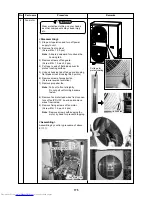
2. Fan-IPDU
Procedure
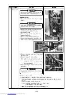
<Disassembling>
1) Stop the unit operation and turn off the
power supply to the unit.
WARNING
Never open the cabinet while five
minutes after turn off the power supply.
2) Remove front cabinet.
(Screw Ø4 × 10 3 pcs)
3) Open I/F P.C. board on the slant.
(Screw Ø4 × 8 2 pcs and supporter)
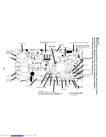
4) Remove wires to fan-IPDU.
(Fan motor, CN01, CN02, CN03, CN04,
CN804)
5) Remove fan-IPDU. (Supporter 4 points)
<Assembling>
Assembling by contrary procedure of above
5)
→
1).
Remarks
3. Comp-IPDU
<Disassembling>
1) Stop the unit operation and turn off the
power supply to the unit.
WARNING
Never open the cabinet while five
minutes after turn off the power supply.
2) Remove fan-IPDU by procedure 3 – 2.
3) Remove front side wires of comp-IPDU.
(Compressor lead wires and high pres-
sure SW wires)
4) Remove fix screws of comp-IPDU.
(For heat sink and for P.C. board fixing)
5) Slide out comp-IPDU to front side.
Note : Slide little hard, for sealing cement
of heat sink.
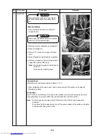
6) Remove wires from comp-IPDU to other
parts. (LIVE, NEUTRAL, CAPA+, CAPA–)
7) Remove other wires.
<Assembling>
Assembling by contrary procedure of above
7)
→
1).
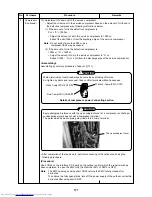
CAUTION
• Fix it to IPDU after letting “LIVE”
wiring pass to ACCT (current sensor).
• After IPDU applies silicon grease to a
contact surface with a heat sink
uniformly, fix it to a heat sink firmly
with a screw.
Screw
The screw for
heat sink fixation
The screw for
heat sink fixation
Screw
Silicoe grease
Silicon grease
NEUTRAL
CAPA +
ACCT
LIVE
CAPA –
Comp-IPDU
The screw for
heat sink fixation
The screw for
heat sink fixation
Comp-IPDU
Compressor lead
U : CN09
→
Red
V : CN10
→
White
W : CN11
→
Black
Compressor lead
U : CN09
→
Red
V : CN10
→
White
W : CN11
→
Black
CN01, CN02
CN804
Fan motor
CN03
CN04
Fan-IPDU
Fan motor
CN01, CN02
CN804
Fan-IPDU
Fan motor

