3-29
CHAPTER 3 SADDLE STITCHER UNIT BASIC OPERATION
2.
Stitcher Unit Operation
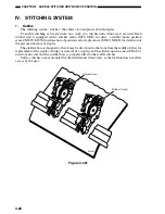
The stitcher base unit consists of two stitchers and stitcher bases. The stitchers are fixed in
position, and are not designed to slide or swing.
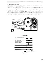
Stitching is executed by driving the rotary cam by the stitcher motor (M7S, M6S). The front
and rear stitcher units are operated with a time delay so as to prevent wrinkling of paper and to limit
the load applied to the power supply. (A time delay for initiating the stitcher motor startup current
helps decrease the load on the power supply.)
The stitcher home position sensor (MS7S, MS5S) is used to monitor the movement of the
rotary cam, enabling identification of individual stitcher operations. The presence/absence of staples
inside the staple cartridge fitted to the stitcher is detected by the staple sensor (MS6S, MS4S).
The alignment plates keep both edges of the stack in place while stitching takes place.
Figure 3-402
(MS7S)
(MS5S)
(PI18S)
Stitcher home position sensor
(front)
Stitcher motor (front) (MS7)
Stitcher motor (rear) (M6S)
Stitcher home position
sensor (rear)
No.1 paper sensor
Alignment motor (M5S)
Alignment
Escape
Figure 3-403
Summary of Contents for MJ-1027
Page 1: ...SERVICE MANUAL FINISHER MJ 1027 1028 File No SME040041A0 R04102169300 TTEC Ver01_2007 09 ...
Page 5: ...ii ...
Page 9: ...vi ...
Page 70: ...2 41 CHAPTER 2 FINISHER UNIT BASIC OPERATION Height sensor PS1 Paper Figure 2 240 ...
Page 101: ...3 15 CHAPTER 3 SADDLE STITCHER UNIT BASIC OPERATION Figure 3 301 ...
Page 104: ...3 18 CHAPTER 3 SADDLE STITCHER UNIT BASIC OPERATION 2 A3 LD Paper Path 3 sheets Figure 3 303 ...
Page 116: ...3 30 CHAPTER 3 SADDLE STITCHER UNIT BASIC OPERATION Cam Mount Figure 3 404 ...
Page 173: ...6 CHAPTER 6 TROUBLESHOOTING II ARRANGEMENT OF ELECTRICAL PARTS A Finisher Unit ...
Page 235: ...2 17 2 HIGASHIGOTANDA SHINAGAWA KU TOKYO 141 8664 JAPAN ...


