


3-43
CHAPTER 3 SADDLE STITCHER UNIT BASIC OPERATION
VII. POWER SUPPLY
1.
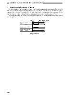
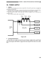
Outline
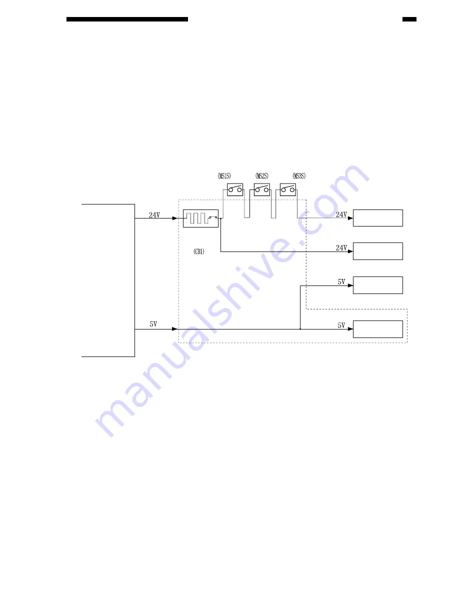
When the host machine power switch is turned ON, 24V and 5V power lines are supplied by
the finisher controller PCB.
The 24V power is used to drive solenoids. The 24V power from the finisher controller PCB to
solenoids does not pass through any protective mechanisms (microswitches, or the like).
The 24V power to motors, on the other hand, will not be supplied if any of the three door
switches is open.
The 5V power is used to drive sensors and ICs.
J19-1
J3-2
J1-1
J2-5
Finisher
controller
PCB
Circuit
breaker
Saddle stitcher
controller PCB
Inlet door
switch
Front door
switch
Delivery
door switch
Motor systems
Solenoids
Sensors
Logic
Figure 3-701
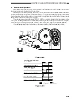
2.
Protective Mechanisms
The 24 VDC power supply used for motors and solenoids is equipped with a circuit breaker
(CB1). The 24V power supply used to drive the feed motor (M1S), alignment motor (M5S), and the
paper positioning plate motor (M4S) is equipped with a fuse designed to blow when an overcurrent
flows.
Summary of Contents for MJ-1027
Page 1: ...SERVICE MANUAL FINISHER MJ 1027 1028 File No SME040041A0 R04102169300 TTEC Ver01_2007 09 ...
Page 5: ...ii ...
Page 9: ...vi ...
Page 70: ...2 41 CHAPTER 2 FINISHER UNIT BASIC OPERATION Height sensor PS1 Paper Figure 2 240 ...
Page 101: ...3 15 CHAPTER 3 SADDLE STITCHER UNIT BASIC OPERATION Figure 3 301 ...
Page 104: ...3 18 CHAPTER 3 SADDLE STITCHER UNIT BASIC OPERATION 2 A3 LD Paper Path 3 sheets Figure 3 303 ...
Page 116: ...3 30 CHAPTER 3 SADDLE STITCHER UNIT BASIC OPERATION Cam Mount Figure 3 404 ...
Page 173: ...6 CHAPTER 6 TROUBLESHOOTING II ARRANGEMENT OF ELECTRICAL PARTS A Finisher Unit ...
Page 235: ...2 17 2 HIGASHIGOTANDA SHINAGAWA KU TOKYO 141 8664 JAPAN ...


