


6-7
CHAPTER 6 TROUBLESHOOTING
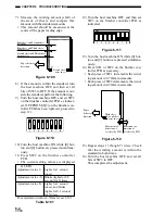
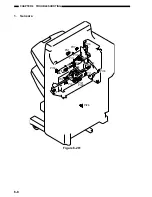
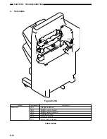
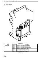
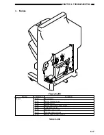
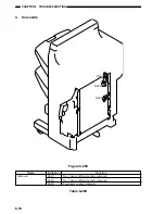
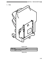
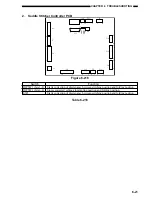
3. Motors
M7S
M8S
M2S
M1S
M4S
M5S
M3S
M6S
Figure 6-208
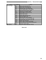
Name
Notation
Function
Motor
M1S
Feed motor
M2S
Paper folding motor
M3S
Guide motor
M4S
Paper positioning plate motor
M5S
Alignment motor
M6S
Stitcher motor (rear)
M7S
Stitcher motor (front)
M8S
Paper pushing plate motor
Table 6-208
Summary of Contents for MJ-1027
Page 1: ...SERVICE MANUAL FINISHER MJ 1027 1028 File No SME040041A0 R04102169300 TTEC Ver01_2007 09 ...
Page 5: ...ii ...
Page 9: ...vi ...
Page 70: ...2 41 CHAPTER 2 FINISHER UNIT BASIC OPERATION Height sensor PS1 Paper Figure 2 240 ...
Page 101: ...3 15 CHAPTER 3 SADDLE STITCHER UNIT BASIC OPERATION Figure 3 301 ...
Page 104: ...3 18 CHAPTER 3 SADDLE STITCHER UNIT BASIC OPERATION 2 A3 LD Paper Path 3 sheets Figure 3 303 ...
Page 116: ...3 30 CHAPTER 3 SADDLE STITCHER UNIT BASIC OPERATION Cam Mount Figure 3 404 ...
Page 173: ...6 CHAPTER 6 TROUBLESHOOTING II ARRANGEMENT OF ELECTRICAL PARTS A Finisher Unit ...
Page 235: ...2 17 2 HIGASHIGOTANDA SHINAGAWA KU TOKYO 141 8664 JAPAN ...


