6-36
CHAPTER 6 TROUBLESHOOTING
9.
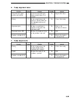
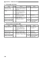
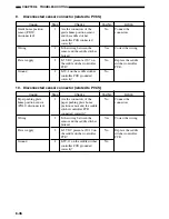
Disconnected sensor connector (related to PI13S)
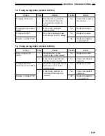
10. Disconnected sensor connector (related to PI14S)
Checks
Are the connectors of the
guide home position sensor
and the saddle stitcher
controller PCB connected
correctly?
Is the wiring between the
sensor and the saddle stitcher
broken?
Is 5 VDC present at J9-7 on
the saddle stitcher controller
PCB?
Is J9-8 on the saddle stitcher
controller PCB grounded
correctly?
Cause
Guide home position
sensor (PI13S;
disconnected)
Wiring
Power supply
Ground
Step
1
2
3
4
Yes/No
No
Yes
No
No
Action
Connect the
connectors.
Correct the wiring.
Replace the saddle
stitcher controller
PCB.
Checks
Are the connectors of the
paper pushing plate home
position sensor and the saddle
stitcher controller PCB
connected correctly?
Is the wiring between the
sensor and the saddle stitcher
broken?
Is 5 VDC present at J9-10 on
the saddle stitcher controller
PCB?
Is J9-11 on the saddle stitcher
controller PCB grounded
correctly?
Cause
Paper pushing plate
home position sensor
(PI14S; disconnected)
Wiring
Power supply
Ground
Step
1
2
3
4
Yes/No
No
Yes
No
No
Action
Connect the
connectors.
Correct the wiring.
Replace the saddle
stitcher controller
PCB.
Summary of Contents for MJ-1027
Page 1: ...SERVICE MANUAL FINISHER MJ 1027 1028 File No SME040041A0 R04102169300 TTEC Ver01_2007 09 ...
Page 5: ...ii ...
Page 9: ...vi ...
Page 70: ...2 41 CHAPTER 2 FINISHER UNIT BASIC OPERATION Height sensor PS1 Paper Figure 2 240 ...
Page 101: ...3 15 CHAPTER 3 SADDLE STITCHER UNIT BASIC OPERATION Figure 3 301 ...
Page 104: ...3 18 CHAPTER 3 SADDLE STITCHER UNIT BASIC OPERATION 2 A3 LD Paper Path 3 sheets Figure 3 303 ...
Page 116: ...3 30 CHAPTER 3 SADDLE STITCHER UNIT BASIC OPERATION Cam Mount Figure 3 404 ...
Page 173: ...6 CHAPTER 6 TROUBLESHOOTING II ARRANGEMENT OF ELECTRICAL PARTS A Finisher Unit ...
Page 235: ...2 17 2 HIGASHIGOTANDA SHINAGAWA KU TOKYO 141 8664 JAPAN ...

