

2-43
CHAPTER 2 FINISHER UNIT BASIC OPERATION
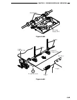
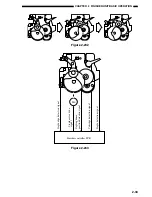
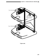
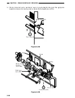
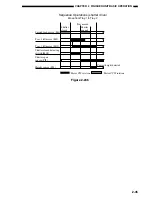
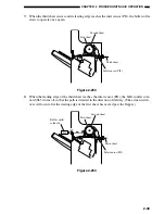
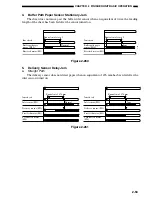
2) The tray-1,-2 lift motor rotates, and the new tray moves to the stacking lower limit. The dis-
tance of movement is detected by1 the tray-1 lift motor clock sensor 1/2 (PI9/19) or tray-2 lift
motor clock sensor 1/2 (PI22/PI24).
Tray-2 lift motor
M10
M5
Tray-1 lift motor
Figure 2-242
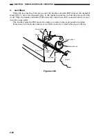
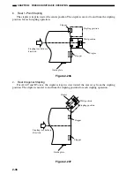
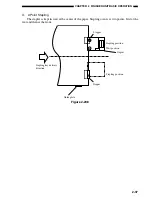
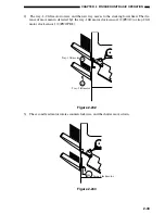
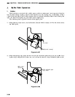
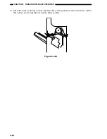
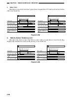
3) The second feed motor rotates counterclockwise, and the shutter moves down.
M8
Second feed motor
Figure 2-243
Summary of Contents for MJ-1027
Page 1: ...SERVICE MANUAL FINISHER MJ 1027 1028 File No SME040041A0 R04102169300 TTEC Ver01_2007 09 ...
Page 5: ...ii ...
Page 9: ...vi ...
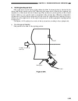
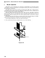
Page 70: ...2 41 CHAPTER 2 FINISHER UNIT BASIC OPERATION Height sensor PS1 Paper Figure 2 240 ...
Page 101: ...3 15 CHAPTER 3 SADDLE STITCHER UNIT BASIC OPERATION Figure 3 301 ...
Page 104: ...3 18 CHAPTER 3 SADDLE STITCHER UNIT BASIC OPERATION 2 A3 LD Paper Path 3 sheets Figure 3 303 ...
Page 116: ...3 30 CHAPTER 3 SADDLE STITCHER UNIT BASIC OPERATION Cam Mount Figure 3 404 ...
Page 173: ...6 CHAPTER 6 TROUBLESHOOTING II ARRANGEMENT OF ELECTRICAL PARTS A Finisher Unit ...
Page 235: ...2 17 2 HIGASHIGOTANDA SHINAGAWA KU TOKYO 141 8664 JAPAN ...


