– 2 –
Contents
Precautions for Safety ................................................................................................ 7
Specifications ............................................................................................................ 13
1 Wiring Diagrams .................................................................................................... 15
1-1. Compact 4-way cassette type ......................................................................................... 15
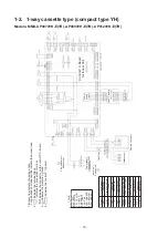
1-2. 1-way cassette type (compact type YH) ......................................................................... 16
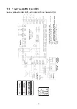
1-3. 1-way cassette type (SH) ................................................................................................. 17
1-4. Concealed duct standard type ........................................................................................ 18
1-5. Concealed duct high static pressure type ..................................................................... 19
1-6. Slim duct type ................................................................................................................... 21
1-7. Ceiling type ....................................................................................................................... 22
1-8. Floor standing cabinet type ............................................................................................ 23
1-9. Floor standing concealed type ....................................................................................... 24
1-10. Floor standing type .......................................................................................................... 25
2 Parts Rating ........................................................................................................... 26
2-1. Indoor unit ......................................................................................................................... 26
3 Refrigerant Cycle Diagram ................................................................................... 30
4 Control Outline ...................................................................................................... 31
5 Applied Control and Functions
(Including Circuit Configuration) ......................................................................... 38
5-1. Indoor controller block diagram ..................................................................................... 38
5-1-1. When main (sub) remote controller connected ................................................................ 38
5-1-2. When wireless remote controller kit connected ............................................................... 40
5-1-3. When both main (sub) remote controller and wireless remote controller kit
connected ............................................................................................................................. 42
5-2. Indoor printed circuit board ............................................................................................ 44
5-3. Optional connector specifications of indoor P.C. board .............................................. 46
5-4. Test operation of indoor unit .......................................................................................... 47
5-5. Method to set indoor unit function DN code ................................................................. 48
5-6. Applied control of indoor unit ......................................................................................... 52
6 Troubleshooting .................................................................................................... 68
6-1. Overview ........................................................................................................................... 68
6-2. Troubleshooting method ................................................................................................. 69
6-3. Troubleshooting based on information displayed on remote controller .................... 75
6-4. Check codes displayed on remote controller and SMMS outdoor unit
(7-segment display on I/F board) and locations to be checked................................... 80
6-5. Sensor characteristics ..................................................................................................... 94
Summary of Contents for MMC-AP0154H-E(-TR)
Page 145: ... 145 ...
Page 149: ... 149 9 2 1 Way cassette type SH 4 2 0 P A 8 1 0 P A 5 1 0 P A ...
Page 156: ... 156 MMU AP0056MH ...
Page 159: ... 159 9 4 Slim duct type MMD AP0054SPH AP0074SPH AP0094SPH AP0124SPH AP0154SPH AP0184SPH ...
Page 162: ... 162 MMD AP0056MH ...
Page 165: ... 165 9 5 Concealed duct standard type MMD AP0074BH AP0094BH AP0124BH AP0154BH AP0184BH ...
Page 166: ... 166 ...
Page 169: ... 169 MMD AP0244BH AP0274BH AP0304BH AP0364BH AP0484BH ...
Page 170: ... 170 ...
Page 173: ... 173 MMD AP0564BH ...
Page 174: ... 174 ...
Page 177: ... 177 E Parts ...
Page 179: ... 179 9 6 Concealed duct high static pressure type MMD AP0184H AP0244H AP0274H AP0364H AP0484H ...
Page 183: ... 183 MMD AP0724H AP0964H ...
Page 184: ... 184 ...
Page 187: ... 187 9 7 Ceiling type MMC AP0154H AP0184H AP0244H AP0274H ...
Page 190: ... 190 MMC AP0364H AP0484H ...
Page 194: ... 194 9 8 Floor standing type MMF AP0154H AP0184H AP0244H AP0274H ...
Page 195: ... 195 MMF AP0154H AP0184H AP0244H AP0274H ...
Page 198: ... 198 MMF AP0364H AP0484H AP0564H ...
Page 199: ... 199 MMF AP0364H AP0484H AP0564H ...
Page 203: ... 203 9 9 Floor standing concealed type MML AP0074BH AP0094BH AP0124BH AP0154BH AP0184BH ...
Page 206: ... 206 MML AP0244BH ...
Page 209: ... 209 9 10 Floor standing cabinet type MML AP0074H AP0094H AP0124H AP0154H AP0184H ...
Page 210: ... 210 MML AP0074H AP0094H AP0124H AP0154H AP0184H ...
Page 213: ... 213 MML AP0244H ...
Page 214: ... 214 MML AP0244H ...


