– 36 –
16
Selection of
central control
mode
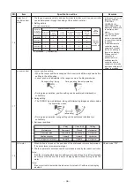
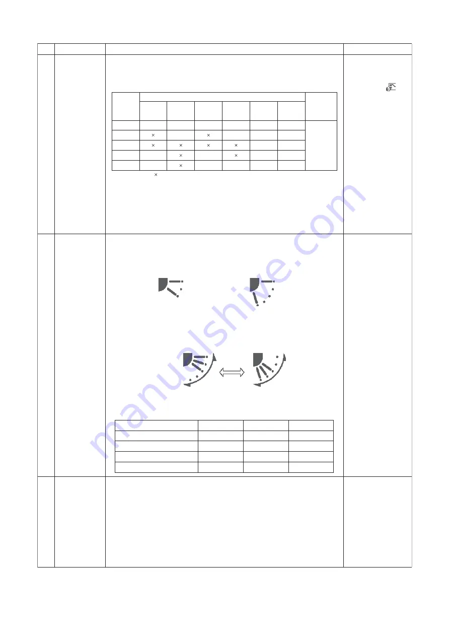
1. The range of operations that can be performed via an indoor unit remote controller
can be determined through the setting of the central controller.
2. Setting details
• In the case of a wired
remote controller,
“CENTRAL
CONTROL IN
PROGRESS
” is
displayed (lit up) while
in central control
mode.
• The display blinks
when a control
function inaccessible
to a remote controller
is chosen.
• A wireless remote
controller has the
same set of control
functions, although
there is no display.
When a control
operation is
performed via a
wireless remote
controller while in
central control mode,
a peep sound alert (5
times) is provided.
17
Louver control
1. Louver position setting
• When the louver position is changed, the louver turns all the way down before
settling in the set position.
• Louver position is adjustable in the range shown in the diagrams below.
• During group operation, position setting can be performed individually or
collectively.
2. Swing setting
• The “SWING” sign is displayed, along with alternating images as shown below.
• During group operation, swing setting can be performed individually or
collectively.
3. Set louver positions
18
DC motor
1. When the fan is turned on, the positions of the stator and rotor are determined.
(The motor turns in incremental steps.)
2. The fan operates in accordance with commands issued by the indoor controller.
Note:
If the fan is rotating while the air conditioner is turned off due to an inflow of outside
air or some other reason, the indoor unit may operate without turning on the fan
motor.
Note:
If fan motor lock is detected, the indoor unit is turned off, with an error display
provided.
Check code “P12”
s
k
r
a
m
e
R
e
n
i
l
t
u
o
n
o
i
t
a
c
i
f
i
c
e
p
S
m
e
t
I
.
O
N
TCC-Link central control
(O: Accessible
: Inaccessible)
Operation
via TCC-
Link central
control
Operation via RBC-AMT32E
RBC-
AMT32E
display
Start / stop
selection
Operation
mode
selection
Timer
setting
Temperature
setting
Fan speed
setting
Air flow
direction
setting
Individual
O
O
O
O
O
O
“CENTRAL
CONTROL
IN
PROGRESS”
Central 1
O
O
O
O
Central 2
O
O
Central 3
O
O
O
O
Central 4
O
O
O
O
O
During cooling / drying
During heating / fan-only operation
In all operation modes
(alternating)
4-way
1-way (SH)
Ceiling
Normal stop
Downward
Closed
Horizontal
Abnormal stop
Downward
No change
Horizontal
Heating standby
Upward
Upward
Horizontal
Oil / refrigerant recovery
Upward
Upward
Horizontal
Summary of Contents for MMC-AP0154H-E(-TR)
Page 145: ... 145 ...
Page 149: ... 149 9 2 1 Way cassette type SH 4 2 0 P A 8 1 0 P A 5 1 0 P A ...
Page 156: ... 156 MMU AP0056MH ...
Page 159: ... 159 9 4 Slim duct type MMD AP0054SPH AP0074SPH AP0094SPH AP0124SPH AP0154SPH AP0184SPH ...
Page 162: ... 162 MMD AP0056MH ...
Page 165: ... 165 9 5 Concealed duct standard type MMD AP0074BH AP0094BH AP0124BH AP0154BH AP0184BH ...
Page 166: ... 166 ...
Page 169: ... 169 MMD AP0244BH AP0274BH AP0304BH AP0364BH AP0484BH ...
Page 170: ... 170 ...
Page 173: ... 173 MMD AP0564BH ...
Page 174: ... 174 ...
Page 177: ... 177 E Parts ...
Page 179: ... 179 9 6 Concealed duct high static pressure type MMD AP0184H AP0244H AP0274H AP0364H AP0484H ...
Page 183: ... 183 MMD AP0724H AP0964H ...
Page 184: ... 184 ...
Page 187: ... 187 9 7 Ceiling type MMC AP0154H AP0184H AP0244H AP0274H ...
Page 190: ... 190 MMC AP0364H AP0484H ...
Page 194: ... 194 9 8 Floor standing type MMF AP0154H AP0184H AP0244H AP0274H ...
Page 195: ... 195 MMF AP0154H AP0184H AP0244H AP0274H ...
Page 198: ... 198 MMF AP0364H AP0484H AP0564H ...
Page 199: ... 199 MMF AP0364H AP0484H AP0564H ...
Page 203: ... 203 9 9 Floor standing concealed type MML AP0074BH AP0094BH AP0124BH AP0154BH AP0184BH ...
Page 206: ... 206 MML AP0244BH ...
Page 209: ... 209 9 10 Floor standing cabinet type MML AP0074H AP0094H AP0124H AP0154H AP0184H ...
Page 210: ... 210 MML AP0074H AP0094H AP0124H AP0154H AP0184H ...
Page 213: ... 213 MML AP0244H ...
Page 214: ... 214 MML AP0244H ...


