background image

– 21 –

SMMS Floor Standing Type

Installation Manual

SMMS Floor Standing Type

Installation Manual

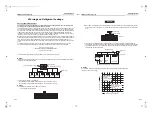
Warnings on Refrigerant Leakage

Check of Concentration Limit

The room in which the air conditioner is to be installed requires a design that in the event of refrigerant 
gas leaking out, its concentration will not exceed a set limit.

The refrigerant R410A which is used in the air conditioner is safe, without the toxicity or combustibility of ammonia, 
and is not restricted by laws to be imposed which protect the ozone layer. However, since it contains more than 
air, it poses the risk of suffocation if its concentration should rise excessively. Suffocation from leakage of R410A 
is almost non-existent. With the recent increase in the number of high concentration buildings, however, the 
installation of multi air conditioner systems is on the increase because of the need for effective use of floor space, 
individual control, energy conservation by curtailing heat and carrying power etc.
Most importantly, the multi air conditioner system is able to replenish a large amount of refrigerant compared with 
conventional individual air conditioners. If a single unit of the multi conditioner system is to be installed in a small 
room, select a suitable model and installation procedure so that if the refrigerant accidentally leaks out, its 
concentration does not reach the limit (and in the event of an emergency, measures can be made before injury can 
occur).
In a room where the concentration may exceed the limit, create an opening with adjacent rooms, or install 
mechanical ventilation combined with a gas leak detection device.The concentration is as given below.

The concentration limit of R410A which is used in multi air conditioners is 0.3 kg/m

3

.

NOTE 1

If there are 2 or more refrigerating systems in a single refrigerating device, the amounts of refrigerant should be as 
charged in each independent device.

For the amount of charge in this example:

The possible amount of leaked refrigerant gas in rooms A, B and C is 10 kg.
The possible amount of leaked refrigerant gas in rooms D, E and F is 15 kg.

NOTE 2

The standards for minimum room volume are as follows.

1) No partition (shaded portion)

Total amount of refrigerant (kg)

Min. volume of the indoor unit installed room (m

3

)

 Concentration limit (kg/m

3

)

e.g., charged amount (10 kg)

e.g., charged amount (15 kg)

Outdoor unit

Indoor unit

Room A

Room B

Room C

Room D

Room E

Room F

2) When there is an effective opening with the adjacent room for ventilation of leaking refrigerant gas (opening 

without a door, or an opening 0.15 % or larger than the respective floor spaces at the top or bottom of the 
door).

3) If an indoor unit is installed in each partitioned room and the refrigerant piping is interconnected, the 

smallest room of course becomes the object. But when a mechanical ventilation is installed interlocked with 
a gas leakage detector in the smallest room where the density limit is exceeded, the volume of the next 
smallest room becomes the object.

NOTE 3

The minimum indoor floor area compared with the amount of refrigerant is roughly as follows:
(When the ceiling is 2.7 m high)

Important

Refrigerant piping

Indoor unit

Outdoor unit

Outdoor unit

Very small room

Refrigerant piping

Indoor unit

Mechanical ventilation device - Gas leak detector

Small 

room

Medium 

room

Large room

0

5

10

10

20

30

15

20

25

30

35

40

m

2

kg

M

in. i

ndo

or floor

 ar

ea

Range above the 

density limit of 0.3 kg/m

3

(countermeasures 

needed)

Range below the 

density limit of 


0.3 kg/m

3

(countermeasures 

not needed)

Total amount of refrigerant

41-EN

42-EN

+00EH99880501_01EN.book  Page 21  Thursday, April 7, 2011  10:15 AM

Summary of Contents for MMC-AP0154H-TR

Page 1: ...4H E MMF AP0484H E MMF AP0564H E Indoor Unit Model name Floor Standing Type MMF AP0154H E MMF AP0184H E MMF AP0244H E MMF AP0274H E AIR CONDITIONER MULTI TYPE Installation Manual 00EH99880501_01EN book Page 1 Thursday April 7 2011 10 15 AM ...

Page 2: ...ved in installation relocation and removal has the qualifications pertaining to this refrigerant handling and piping work as stipulated by the local laws and regulations and he or she is a person who has been trained in matters relating to refrigerant handling and piping work on the air conditioners made by Toshiba Carrier Corporation or alternatively he or she has been instructed in such matters ...

Page 3: ...cap Repair of outdoor unit Gloves to provide protection for electricians and from heat Warning indications on the air conditioner unit Warning indication Description WARNING ELECTRICAL SHOCK HAZARD Disconnect all remote electric power supplies before servicing WARNING Moving parts Do not operate unit with grille removed Stop the unit before the servicing CAUTION High temperature parts You might ge...

Page 4: ...acking carton You may injure yourself if the bands should break Do not place any combustion appliance in a place where it is directly exposed to the wind of air conditioner otherwise it may cause imperfect combustion Installation Install the air conditioner securely in a location where the base can sustain the weight adequately If the strength is not enough the unit may fall down resulting in inju...

Page 5: ...act a qualified service person 1 to have the repairs done Do not set the circuit breaker to the ON position until the repairs are completed Relocation Only a qualified installer 1 or qualified service person 1 is allowed to relocate the air conditioner It is dangerous for the air conditioner to be relocated by an unqualified individual since a fire electric shocks injury water leakage noise and or...

Page 6: ... the plastic parts to be damaged and other such problems to result Locations near obstructions such as ventilation openings or lighting fixtures where the flow of the blown air will be disrupted a disruption of the air flow may cause the air conditioner s performance to deteriorate or the unit to shut down Locations where an in house power generator is used for the power supply The power line freq...

Page 7: ...or immediately for safety Installation of indoor unit Fixing to the wall surface Use the attached wall fixing bracket by inverting it at upper side of the unit Fix the indoor unit to the wall surface using the attached screw bolts anchor bolts or etc at two positions A many holes for fixing the indoor unit to wall surface and for fixing the indoor unit itself are provided on the bracket Sliding th...

Page 8: ... room Air intake grille Bracket for fixing to floor Bracket for fixing to wall Electrical control box cover Vertical louver Turn the vertical louver while lifting up lightly and then insert it into the clearance of extrusion of the coupling rod Extrusion Coupling rod 8 m or less 5 Drain Piping CAUTION Following the Installation Manual perform the drain piping work so that water is properly drained...

Page 9: ...5 mm or more on AP015 to AP027 model If the clearance is less than 5 mm drip proof cover cannot be removed and the electrical control box cannot be took out Drain hose Drain pan Heat insulator Hart polyvinyl chloride pipe Adhesion for hart polyvinyl chloride pipe used To connect drain hose on right route it through the knock out for refrigerant piping on AP015 to AP027 model Power supply wire take...

Page 10: ...12 7 16 6 15 9 19 7 Use two wrenches to connect the indoor unit pipe Use the tightening torque levels as listed in the following table Tightening torque of flare pipe connections Pressure of R410A is higher than that of R22 Approx 1 6 times Therefore using a torque wrench tighten the flare pipe connecting sections which connect the indoor and outdoor units of the specified tightening torque Incorr...

Page 11: ...the power supply specifications follow to the following table If capacity is little it is dangerous because overheat or burnout may be caused For specifications of the power capacity of the outdoor unit and the power supply wires refer to the Installation Manual attached to the outdoor unit Indoor unit power supply For the power supply of the indoor unit prepare the exclusive power supply separate...

Page 12: ...gh voltage circuit How to remove the electrical control box cover AP015 to AP027 models Take off screws 1 and 2 at this side of the electrical control box and remove the drip proof cover Take off screws 3 and 4 at front side of the electrical control box and remove the electrical control box cover AP036 to AP056 models Take off screws 3 and 4 at front side of the electrical control box and remove ...

Page 13: ...on is pushed While air conditioners are operated under the group control ALL is displayed first When is pushed the indoor unit number displayed following ALL is the header unit 1 6 1 3 2 5 4 Display content varies with the indoor unit model 2 Each time button is pushed indoor unit numbers in the control group change cyclically Select the indoor unit to change settings for The fan of the selected u...

Page 14: ...s been performed using this method do NOT forget to release the shorting of CN72 after the test run is completed Operate the unit with the wired remote controller as usual For the procedure of the operation refer to the attached Owner s Manual to the outdoor unit A forced test run can be executed in the following procedure even if the operation stops by thermostat OFF In order to prevent a serial ...

Page 15: ...nd outdoor units regularly will result in poor performance freezing water leakage and even compressor failure 4 1 3 Inspection before maintenance Following inspection must be carried out by a qualified installer or qualified service person Maintenance List Parts Inspection method Heat exchanger Access from inspection opening and remove the access panel Examine the heat exchanger if there is any cl...

Page 16: ...rs The log can be confirmed from both operating status and stop status 1 When and buttons are pushed simultaneously for 4 seconds or more the following display appears If is displayed the mode enters in the error log mode 01 Order of error log is displayed in CODE No Error code is displayed in CHECK Indoor unit address in which an error occurred is displayed in Unit No 2 Every pushing of button us...

Page 17: ...roller E03 97 Communication error between indoor unit and remote controller Detected at indoor unit side Indoor unit E04 04 Communication circuit error between indoor outdoor unit Detected at indoor unit side Indoor unit E06 E06 No of indoor units in which sensor has been normally received 04 Decrease of No of indoor units I F E07 Communication circuit error between indoor outdoor unit Detected at...

Page 18: ... 01 Comp 1 side 02 Comp 2 side 03 Comp 3 side 1d Compressor trouble lock IPDU H03 H03 01 Comp 1 side 02 Comp 2 side 03 Comp 3 side 17 Current detect circuit system error IPDU H04 H04 44 Comp 1 case thermo operation I F H05 H05 TD1 sensor miswiring I F H06 H06 20 Low pressure protective operation I F H07 H07 d7 Oil level down detective protection I F H08 H08 01 TK1 sensor error 02 TK2 sensor error ...

Page 19: ... side 03 Comp 3 side AF ALT Phase missing detection Power failure detection Inverter DC voltage error comp Inverter DC voltage error comp Inverter DC voltage error comp I F P07 P07 01 Comp 1 side 02 Comp 2 side 03 Comp 3 side IC ALT Heat sink overheat error IPDU I F P09 P09 Detected heat storage address 47 ALT No heat storage unit water error Heat storage unit P10 P10 Detected indoor unit address ...

Page 20: ...mp 2 Comp 3 Fan Check code Wireless remote controller Check code name Judging device Central control device indication Outdoor unit 7 segment display AI NET central control display Sensor block display of receiving unit Auxiliary code Operation Timer Ready Flash C05 Sending error in TCC LINK central control device TCC LINK C06 Receiving error in TCC LINK central control device TCC LINK C12 Batch a...

Page 21: ...r Nick Ball Toshiba EMEA Engineering Director Toshiba Carrier UK Ltd Porsham Close Belliver Industrial Estate PLYMOUTH Devon PL6 7DB United Kingdom Hereby declares that the machinery described below Generic Denomination Air Conditioner Model type MMF AP0154H E MMF AP0184H E MMF AP0244H E MMF AP0274H E MMF AP0364H E MMF AP0484H E MMF AP0564H E Commercial name Super Modular Multi System Air Conditio...

Page 22: ...ulti air conditioners is 0 3 kg m3 NOTE 1 If there are 2 or more refrigerating systems in a single refrigerating device the amounts of refrigerant should be as charged in each independent device For the amount of charge in this example The possible amount of leaked refrigerant gas in rooms A B and C is 10 kg The possible amount of leaked refrigerant gas in rooms D E and F is 15 kg NOTE 2 The stand...

Page 23: ...nd fill check mark in ITEM if changed respectively For check method refer to APPLICABLE CONTROLS in this manual Filter sign lighting time CODE NO 01 F NO CHANGE F NONE 0000 F 150H 0001 F 2500H 0002 F 5000H 0003 F 10000H 0004 Filter sign lighting time CODE NO 01 F NO CHANGE F NONE 0000 F 150H 0001 F 2500H 0002 F 5000H 0003 F 10000H 0004 Filter sign lighting time CODE NO 01 F NO CHANGE F NONE 0000 F...

Page 24: ...EH99880599 00EH99880501_01EN book Page 23 Thursday April 7 2011 10 15 AM ...

Reviews: