background image

3-170

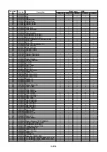
Model name     MMD-

Location

No.

Part No.

Description

P0151H

P0181H

P0241H

P0361H

P0481H

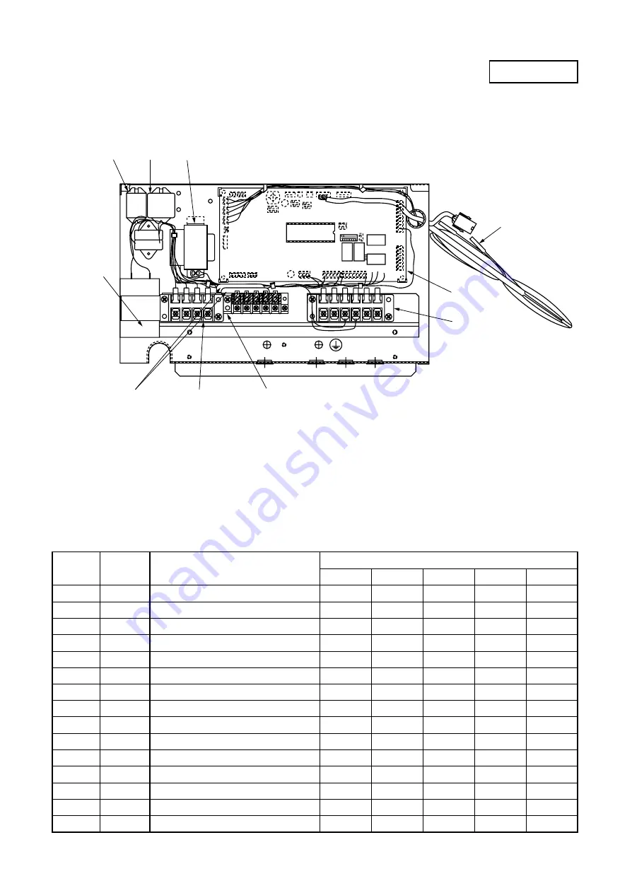
401

43158166 Transformer, Power, ST-11227

1

1

1

1

402

43160427 Terminal, 5P

1

1

1

1

403

43160469 Terminal, Block, 6P

1

1

1

1

404

43160341 Terminal, Block, 4P

1

1

1

1

405

43155164 Capacitor

1

406

43155142 Capacitor, 4µFD, 450V

1

407

43155137 Capacitor

1

408

43155134 Capacitor, MF, EAG45M605UF1

1

409

43154141 Relay, LY2F-L, AC230V

1

1

1

1

410

43154135 Relay, LY3F-JT, AC230V

1

1

1

1

411

43150241 Sensor

1

1

1

1

412

43150200 Sensor, TA

1

1

1

1

413

43150223 Sensor

1

1

1

1

414

4316V046 P.C. Board Ass’y

1

1

1

1

415

43060700 Fuse, 10A, 250V

2

2

2

2

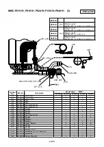
RC

(A)

43F1

R

S

1

2

11 12

F1 F2 F3 F4

A B C P Q

(A)

43F2

Tr

409

410

401

405
406
407
408

415

404

402

414

403

411
412
413

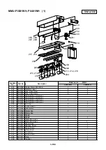
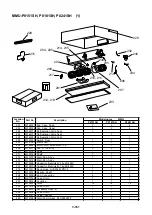
MMD-P0151H, P0181H, P0241H, P0361H, P0481H    (2)

TENTATIVE

Summary of Contents for MMC-P0151H

Page 1: ...ure Type MMD P0181H P0241H P0361H MMD P0481H P0721H P0961H Under Ceiling Type MMC P0151H P0181H P0241H MMC P0361H P0481H High Wall Type MMK P0091H P0121H P0151H MMK P0181H P0241H Floor Standing Cabinet Type MML P0091H P0151H P0181H MML P0241H Floor Standing Concealed Type MML P0091BH P0151BH MML P0181BH P0241BH SERVICE MANUAL FILE NO A02 009 Outdoor Unit Cooling Only Model Inverter Unit MMY MP0801...

Page 2: ...s to be installed requires a design that in the event of refrigerant gas leaking out its concentration will not exceed a set limit The refrigerant R407C which is used in the air conditioner is safe without the toxicity or combustibility of ammonia and is not restricted by laws to be imposed which protect the ozone layer However since it contains more than air it poses the risk of suffocation if it...

Page 3: ...CONFIGURATION 3 107 3 8 EMERGENCY OPERATION 3 131 3 9 FORCED FUNCTION OF OIL LEVEL DETECTION OUTDOOR UNIT 3 135 3 10 REFRIGERANT RECOVERY METHOD WHEN REPLACING THE COMPRESSOR 3 136 3 11 REPLACEMENT OF COMPRESSOR 3 140 3 12 REPLACING METHOD OF PARTS 3 146 3 13 EXPLODED VIEWS AND PARTS LIST 3 148 This Manual is used for both models Cooling Only model and Heat Pump model Positions shaded with screens...

Page 4: ...Install the unit in the prescribed manner to withstand strong hurricane level winds and earthquakes Insufficiently secure installation could allow the unit to tip over fall or otherwise cause an accident Ventilate the area if any refrigerant leaks during installation If the refrigerant comes into contact with an open flame it will produce a toxic gas After completing installation make sure that no...

Page 5: ...n of the unit A location that provides enough space to service the unit safely A location where water draining from the unit will not pose a problem Avoid the following types of locations Locations where salt is present in large amounts seaside areas or where sulfuric gases are present in large amounts hot springs areas If the unit is to be used in such areas special maintenance is necessary Locat...

Page 6: ...otor valve EDM B252TF 1 F25 B402TF 1 F40 Pressure sensor 150F 160NH6 D Louver motor Panel MT 8 3 4 Concealed Duct Type Model MMD P0071BH P0091BH P0121BH P0151BH P0181BH P0241BH P0301BH P0361BH P0481BH Fan motor STF 200 60 4D 200 60 4C 200 100 4E 200 100 4F 200 120 4D 200 140 4G Running capacitor for fan motor 450V 2µF 500V 2 5µF 400V 5 0µF 400V 6µF 400V 10µF Control P C board Transformer TT 03 Flo...

Page 7: ...EV202DXF Main unit NEV MOAJ510B0 Coil AC220 240V 2 way valve NEV603DXF Main unit NEV MOAJ510B0 Coil AC220 240V Outdoor controller Model name or rating Part name MMY MP0801T8 8HP inverter MMY MP1001T8 10HP inverter MMY MP06018 6HP fixed speed MMY MP08018 8HP fixed speed MMY MP10018 10HP fixed speed Power supply voltage 3 Phase AC380 400 415V 50Hz Power supply terminal block 60A 3P 1pc and 30A 3P 1p...

Page 8: ...0712 Main unit CHV 0401 Main unit CHV 0712 Main unit 4 way valve CHV 01AJ502E1 Coil AC220 240V NEV202DXF Main unit NEV MOAJ510B0 Coil AC220 240V 2 way valve NEV603DXF Main unit NEV MOAJ510B0 Coil AC220 240V Outdoor controller Model name or rating Part name MMY MP0801HT8 8HP inverter MMY MP1001HT8 10HP inverter MMY MP0601H8 6HP fixed speed MMY MP0801H8 8HP fixed speed MMY MP1001H8 10HP fixed speed ...

Page 9: ... 0712 Main unit CHV 0401 Main unit CHV 0712 Main unit 4 way valve CHV 01AJ502E1 Coil AC220 240V NEV202DXF Main unit NEV MOAJ510B0 Coil AC220 240V 2 way valve NEV603DXF Main unit NEV MOAJ510B0 Coil AC220 240V Outdoor controller Model name or rating Part name MMY MP0801HT7 8HP inverter MMY MP1001HT7 10HP inverter MMY MP0601H7 6HP fixed speed MMY MP0801H7 8HP fixed speed MMY MP1001H7 10HP fixed speed...

Page 10: ...tails consult with the dealer which you have purchased the air conditioner Air filter Removes dust and trash Air filter is provided in the air grille Air inlet grille Air in the room is sucked from here Earth screw It is included in the electric parts box Clip The clip is to open close the air inlet grille Center panel Air inlet Air in the room is sucked from here Air filter Removes dust and trash...

Page 11: ...uded in the electric parts box Air inlet Air in the room is sucked from here 1 way Air Discharge Cassette Type 1 way Air Discharge Cassette Type Concealed Duct type Concealed Duct High Static Pressure Type Air outlet Discharge louver Select air blow direction in cooling or heating operation each Earth screw It is included in the electric parts box Air inlet grille Air in the room is sucked from he...

Page 12: ...sucked from here Earth screw Earth screws are provided in the electric parts box Air inlet grille Air in the room is sucked from here Air outlet Drain receiver With strainer It is an accessory part which is attached at site Air filter Removes dust and trash Air filter is provided in the air inlet grille Air outlet grille Discharge louver Select air blow direction in cooling or heating operation ea...

Page 13: ...louver function LOUVER display It is displayed while the discharge louver operates in AUTO mode FILTER display If FILTER is displayed clean the air filter PREHEAT DEFROST display Displayed when heating operation or defrost operation starts Unit No in which error fault is displayed in the set up temp display section The selected set up temp is displayed MODE MODE FAN AN TEMP TEMP F A N A N C O O L ...

Page 14: ...ear though other displays remain as they are Louver operation switch In case of Model with auto louver the discharge louver operates or stops during operation of air conditioner Set up on central remote controller Last push priority No display Center Operation inhibit CENTRAL display on standard remote controller Goes off Goes on Flashes Functions operated by standard remote controller Operated fr...

Page 15: ...ws 2 Select air volume with the FAN button One push of the button and the display changes as follows Air volume cannot be selected in the concealed duct type When air volume is AUTO power of air differs according to the room temperature 3 Determine the set up temperature by pushing the TEMP button 4 Push ON OFF button The operation lamp goes on and the operation starts STOP Push ON OFF button The ...

Page 16: ...right only so confirm before removing Remove the fall preventing strings at both ends Pull the air filter downward to remove it In case of MMU P0361WH or MMU P0481WH pull the air filter downward undoing the clips CAUTION Be sure to attach the fall preventing strings of the center panel after cleaning If the center panel drops injury may occur 1 way Air Discharge Cassette Type Undo clip of the suct...

Page 17: ...ipe them with soft and dry cloth If stain of the main unit is heavy wipe out stain with cloth wet in tepid water For remote control wipe outstain with dry cloth without using water Do not use benzene thinner polishing powder or chemical floor cloth because they may cause deformation or crack on the panel or remote controller When the air conditioner is not used for a month or longer Perform fan op...

Page 18: ... operation n Diligent cleaning of air filter If the air filter is clogged cooling heating effect decreases n Close windows and doors often Close windows and doors so that cool air does not blow through the room WARNING Do not expose your body directly in cool air for a long time It may affect the health Especially be watchful for person physically handicapped children or senior person n Room tempe...

Page 19: ...ed to prevent discharge of hot air Since refrigerant is flowed temporarily to prevent stay of oil or refrigerant in the stand by indoor unit sound of flowing refrigerant Kyururu or Shaa may be heard or white steam when other indoor unit operates in HEAT mode and cold air in COOL mode may be blow out Sound is generated when the expansion valve operates when power has been turned on Is the timer ON ...

Page 20: ...not read the display sufficiently push CHECK switch again n Check servicing Though differed according to use status when the air conditioner has been used for several seasons inside of the air conditioner may be stained and performance may decrease Separated from daily maintenance a check servicing charged is recommended The Ceiling cassette type air conditioner incorporates a drain pump If it is ...

Page 21: ...iner Strainer Oil separator Liquid tank Capillary Capillary Capillary Capillary Capillary Solenoid valve SV3A Solenoid valve SV3B Check valve Check valve Check valve Check valve Check valve Check valve Compressor case oil removal valve Packed valve balancing pipe Packed valve liquid side Service valve gas side High pressure SW Solenoid valve SV42 Solenoid valve SV2 4 Way valve Solenoid valve SV3C ...

Page 22: ...k valve Check valve Check valve Check valve Compressor case oil removal valve Packed valve balancing pipe Packed valve liquid side Service valve gas side High pressure SW Solenoid valve SV41 Solenoid valve SV42 Solenoid valve SV2 4 Way valve Solenoid valve SV3C Accumulator Right side Air heat exchanger at outdoor side Left side Air heat exchanger at outdoor side Oil tank HP High pressure SW Fixed ...

Page 23: ... Check valve Check valve Check valve Check valve Check valve Compressor case oil removal valve Packed valve balancing pipe Packed valve liquid side Service valve gas side Solenoid valve SV41 Solenoid valve SV2 4 Way valve Solenoid valve SV3C Accumulator Right side Air heat exchanger at outdoor side Left side Air heat exchanger at outdoor side Oil tank HP High pressure SW Fixed speed Capillary They...

Page 24: ...e fixed speed units stop 3 Liquid line counter pressure preventive control function during defrost operation 4 Fixed with FULL OPEN in cooling operation Pulse motor valve 2 PMVB PMV3 Cooling bypass Connector CN302 Red 1 Liquid bypass proportional control function for releasing discharge temperature Adjustment of refrigerant drying degree during inner reducing operation 2 Releases low pressure Oil ...

Page 25: ...rainer Oil separator Liquid tank Capillary Capillary Capillary Capillary Capillary Solenoid valve SV3A Solenoid valve SV3B Check valve Check valve Check valve Check valve Check valve Check valve Compressor case oil removal valve High pressure SW Solenoid valve SV42 Solenoid valve SV2 4 Way valve Solenoid valve SV3C Accumulator Right side Air heat exchanger at outdoor side Left side Air heat exchan...

Page 26: ...Solenoid valve SV3A Solenoid valve SV3B Check valve Check valve Check valve Check valve Check valve Check valve Compressor case oil removal valve High pressure SW Solenoid valve SV42 Solenoid valve SV2 4 Way valve Solenoid valve SV3C Accumulator Right side Air heat exchanger at outdoor side Left side Air heat exchanger at outdoor side Oil tank HP High pressure SW Inverter Fixed speed Compressor M ...

Page 27: ... Check valve Check valve Check valve Check valve Check valve Check valve Compressor case oil removal valve High pressure SW Solenoid valve SV42 Solenoid valve SV2 4 Way valve Solenoid valve SV3C Accumulator Right side Air heat exchanger at outdoor side Left side Air heat exchanger at outdoor side Oil tank HP High pressure SW Inverter Fixed speed Compressor M HP Propeller fan Fan motor Sensor TE1 C...

Page 28: ...r case oil removal valve High pressure SW Solenoid valve SV42 Solenoid valve SV2 4 Way valve Solenoid valve SV3C Accumulator Right side Air heat exchanger at outdoor side Left side Air heat exchanger at outdoor side Oil tank HP High pressure SW Inverter Fixed speed Compressor M HP Propeller fan Fan motor Sensor TE1 Capillary Pulse motor valve A PMV 1 PMV 2 Pulse motor valve B Cooling bypass PMV 3 ...

Page 29: ...ull close Full close Specified opening Operation start Operation signal from indoor Inverter drive Outdoor fan output Fixed speed MG SW output Each solenoid valve output 4 way valve output OFF in cooling operation PMV A output Operation signal from indoor Inverter drive Outdoor fan output Fixed speed MG SW output Each solenoid valve output 4 way valve output OFF in cooling operation PMV A output O...

Page 30: ... suppressing discharge temp increase or compressor internal temp increase 1 Opening is controlled with pulses from 0 to 500 2 PMV opening is controlled with temp detected by TS TD sensors 3 PMV openings are fully closed during thermostat OFF operation stop and emergency stop Interval control Pd pressure MPa 2 2 2 1 2 0 1 9 1 8 1 7 1 6 1 5 1 4 1 3 1 2 1 1 Max 16 waves 1 wave 20 sec From 2 waves to ...

Page 31: ...he present temperature detected by TK1 TK2 and TK3 sensors are stored in memory as the initial value and then on the solenoid valve SV3C is activated After then execute sampling of TK1 TK2 and TK3 sensor temperature and obtain the temperature change value of TK1 and TK2 Also whether the oil level is adequate or not is judged from relation between the set up oil level judgment time and the above te...

Page 32: ...detected for a long time Recovery time Approx 2 min to 6 min though it differs according to the system capacity The recovery time differs according to the load condition However it is usually executed for 2 to 10 minutes 1 Oil recovery control in cooling room During cooling operation this is executed to recover the refrigerating oil stagnated in gas crossover pipe or indoor unit to the outdoor uni...

Page 33: ...t stop operation have been satisfied and the defrost signal has completed from all the terminal outdoor units 3 Terminal outdoor unit When the common conditions of the defrost stop operation have been satisfied the defrost signal to the master outdoor unit completes The operation shifts to the defrost stop control when the defrost stop conditions have been satisfied and the defrost stop signal has...

Page 34: ... pressure 2 7MPa SV2 is turned off when Pd pressure 2 05MPa 3 Stop conditions In stop time thermostat OFF defrost operation or cooling operation When No 2 compressor of the master outdoor unit is ON When even one of the terminal compressors is ON When the inverter frequency command becomes 51Hz or higher 3 SV2 low pressure release control This control is to prevent quick pressure lowering in trans...

Page 35: ...zone Continuous switch on power B zone Intermittent switch on power ON 10 minutes OFF 5 minutes C zone No switch on power This control is to stop the fixed speed compressor of each outdoor unit according to Pd pressure value This control is individually executed by the master outdoor unit and each server outdoor unit 1 Contents of control The fixed speed compressor stops when Pd pressure is over P...

Page 36: ...ed the heat in outdoor unit or on outdoor fan error is considered 3 Over current protective control 1 The compressor stops when T03 on IPDU control P C board detects over current 2 When the compressor stopped 1 is counted to the error count and the compressor reactivates after 2 minutes 30 seconds After reactivated the error count is cleared if the operation continues for 10 minutes or more 3 The ...

Page 37: ...lowered the freeze prevention control by the indoor unit TC sensor may decrease the frequency 2 When low pressure is lowered the cooling capacity control may decrease the frequency 3 When discharge temp sensor value lowers below 60 C the frequency may be increased over the receive command from the indoor unit 4 No of electro waves of the outdoor fan decreases and a low continuous sound may be hear...

Page 38: ...er A zone Set air volume from remote controller B zone Low air C zone OFF Duct Air volume FIX STOP controls prevention of cold air discharge by TC2 PRE HEAT DEFROST go on HIGH HIGH MED MED LOW LOW COOL HEAT Ts 1 2 1 2 Ts 1 Ultra LOW Compressor OFF 20 16 26 A B C 30 C 1 Frequency correction control Frequency of the outdoor unit is corrected so that the present capacity reaches to the certain specif...

Page 39: ...refrigerant Oil recovery signal is received from the outdoor unit 1 PMV of the indoor unit is opened by a certain degree 2 Fan is stopped 3 Temperature of TC2 is detected and PMV is closed Only for 4 way ceiling cassette type operate the indoor fan for approx 3 to 4 min of the recovery operation On the indoor unit in which thermostat is OFF or which operates with FAN mode PRE HEAT DEFROST go on Fo...

Page 40: ...er indoor unit is under HEAT operation Selection of the operation mode is fixed to COOL or HEAT and an operation reversed to the specification is tried There is an indoor unit which stopped with the indoor overflow alarm 0b 2 The above indoor unit status that cannot operate enters standby status when the thermostat is turned off and this status continues until STANDBY status is released 1 The cont...

Page 41: ...mp TK2 detection error SV3C valve blockage detection SV3C valve leakage detection Outdoor refrigerant leakage detection Indoor address undefined Outdoor address undefined Backup operation stop 21 14 17 1d 1F d3 dA High pressure SW circuit G Tr short circuit protective operation Current detection circuit Compressor error Compressor break down TH sensor circuit Heat sink overheat protective operatio...

Page 42: ...E ON OFF FIL FILTER TER CHECK CHECK MODE FAN TEMP AUT UTO FIX FIX CHECK CHECK ADDRESS ADDRESS UNIT CENTRAL 12 12 F A N A N C O O L C O O L H E A H E AT ST STANDBY ANDBY FILTER PREHEA PREHEAT DEFR DEFROST OST LOUVER MANU MANUAL 3 6 2 Troubleshooting with CHECK Display of Remote Controller 3 6 2 1 In case of main remote controller sub remote controller RBC AM1E RBC AS1E 1 Operation for CHECK display...

Page 43: ...display Display on CHECK monitor FILTER data Example Room temp sensor of No 1 is defective In No 16 first the heat exchanger sensor has failed Next interconnection wire serial signal line of indoor outdoor is defective Case that Filter signal is sent from No 1 and No 16 units under group operation Example There is no check data CHECK code FILTER sign Indoor unit No 2 Reading of CHECK monitor displ...

Page 44: ...riority control CHECK switch Push for 0 5 seconds to display CHECK code Push for 3 seconds to reset indoor microprocessor While indoor microprocessor is locked by ALL STOP alarm Push for 10 seconds to clear check data RESET switch Push the switch in the hole with pin The remote controller resets initialized All data is cleared 3 6 2 2 Remote controller with timer RBC AT1E 1 Operation for CHECK dis...

Page 45: ...ext interconnection wire bus communication line of indoor outdoor is defective Example There is no check data CHECK data UNIT CHECK FILTER UNIT CHECK FILTER UNIT CHECK Unit No Check code detected at first Check code detected at last UNIT CHECK CHECK UNIT CHECK After 3 seconds 0 1 2 3 4 5 6 7 8 9 10 11 12 13 14 15 Hexadecimal notation Decimal notation 7 segment display 2 Reading of CHECK monitor di...

Page 46: ...839404142434445464748 171819 20212223242526272829303132 1 MONITOR SET ZONE ALL CENTER LOCKED AUX TYPE TIMER No STANDBY FILTER ON OFF MODE FANONLY COOL DRY HEAT AUTO ON UNIT 2 3 4 5 6 7 8 9 10111213141516 FAN AUTO HIGH MED LOW FIX TEMP CHECK 1 2 C LOUVER MANUAL LOUVER FAN TEMP MODE MONITOR SET ALL ZONE ZONE UNIT ON CENTER LOCKED CHECK ZONESET ENTER SELECT OFF TIMERON 4950515253545556575859606162636...

Page 47: ...k characteristics of TA sensor resistance value Check failure of indoor main P C board MMC 1361 11 Check connection and wiring of fan connector CN07 CN18 Check running capacitor error for indoor fan Check fan motor error Check indoor P C board error Check effect of outside air process OA 11 4DC Indoor Indoor fan motor alarm Indoor fan motor circuit Status that detection value of motor speed is inc...

Page 48: ...Activation error check by liquid stagnation in compressor Check outdoor P C board IPDU error 1F Outdoor Compressor break down Inverter current detection circuit After inverter frequency reduced by current release over current was detected and stopped Check power supply voltage AC342 457V for 50Hz AC342 418V for 60Hz Check cause of abnormal overload operation Check current sensor detection circuit ...

Page 49: ...ation mode of the system changed to HEAT while backup operation of the outdoor unit was being set up in cooling only model If there is a unit which outdoor backup operation is being set up in cooling only model heating operation is not performed 8d Interface Reduction of No of connected outdoors No of connected outdoor unit communication No of connected outdoor units was judged to be less than No ...

Page 50: ...nits exceeded 40 Connected to other outdoor system or central management remote controller Check No of indoor units connected to outdoor Check connection and miswiring of communication line PQ between indoor and outdoor Check connection of central management remote controller wiring Check connection and miswiring of communication line XY Check outdoor P C board Interface error 97 Indoor BUS commun...

Page 51: ...ng conditions In cooling Room temp 18 to 32 C Outside temp 15 to 43 C In heating Room temp 18 to 32 C Outside temp 15 to 15 C 3 When group operation for other outdoor system is performed miswiring check function cannot be used 9F Indoor Indoor PMV blockage Judgment of refrigerant circulation volume shortage Status that refrigerant did not flow in indoor unit was detected Compared with TA temp TC1 ...

Page 52: ...Pd Ps High pressure Pd sensor and Low pressure Ps sensor were exchanged Output voltage of both sensors are zero Check connection of high pressure Pd sensor connector Check connection of low pressure Ps sensor connector Check pressure sensor Pd and Ps error Check outdoor P C board Interface error Check miswiring of fixed speed compressor terminal Inverse operation of fixed speed scroll compressor C...

Page 53: ...e sensor output was zero After judgment operation transmits to automatic backup operation Check connection and wiring of connector CN23 of indoor pressure sensor and indoor main P C board MCC 1361 Check indoor pressure sensor error Check failure of indoor main P C board MCC 1361 bb Interface Discharge temp TD2 alarm Discharge temp TD2 protection The protective stop when discharge temp TD2 exceeded...

Page 54: ...nnected inverter outdoor units Check SW08 bit 2 set up on outdoor P C board interface Check outdoor P C board interface d2 Interface Fixed speed outdoor unit alarm Fixed speed outdoor unit protection Inverter outdoor unit received an alarm code from fixed speed outdoor Check the check code of fixed speed outdoor unit Convenient functions If keeping SW04 pushed for 5 seconds or more under condition...

Page 55: ... executed Check out of place of TK1 pipe sensor Check characteristics of TK1 sensor resistance value Check misconnection of TK1 TK2 and TK3 d9 Interface TK2 temp detection circuit alarm Oil level detection circuit Temp change at secondary side of oil tank was not detected when oil level detection control was executed Check out of place of TK2 pipe sensor Check characteristics of TK2 sensor resista...

Page 56: ...umper on indoor main P C board MCC 1361 dF Interface Outdoor address undefined During automatic outdoor address There was undefined address in the outdoor addresses Wait for a while during display When the address is defined the operation is automatically reset If the check code does not disappear 5 minutes after turning on the power it is abnormal Check the following items Check indoor P C board ...

Page 57: ...high pressure Pd 2 5MPa High pressure SW system error 1 In case of compressor 1 E1 is displayed 2 In case of compressor 2 F0 is displayed n When high pressure Pd 2 5MPa IOL OCR system error 1 In case of compressor 1 E6 is displayed 2 In case of compressor 2 F1 is displayed Check high pressure SW error of compressor 1 and check IOL OCR operation Check IOL operation of compressor 1 and case temp up ...

Page 58: ... circuit Check outdoor P C board interface error Check indoor PMV opening pulse Check miswiring between indoor outdoor communication line F1 Interface Fixed speed side IOL OL system alarm 2 Fixed speed side IOL OCR system circuit Compressor 2 Fixed speed side IOL OCR system or high pressure SW operated n When high pressure Pd 2 5MPa High pressure SW system error 1 In case of compressor 1 E1 is dis...

Page 59: ... C board is defective Is there no disconnection of communication cable between IPDU and interface P C boards Is communication connector between IPDU and interface P C boards connected Check noise from outside etc Is there voltage deflection between 3 and 5 pins of CN600 on interface P C boards Measurement by tester DC 0 to 5V 5 pin GND Is there voltage deflection between 4 and 5 pins of CN600 on i...

Page 60: ...n wiring of fixed speed compressor Is fixed speed compressor activated Reset power supply and perform trial heating operation Are resistance value characteristics of TS1 and TE1 sensors normal Are output voltage characteristics of Pd and Ps sensors normal Does refrigerant bypass from discharge to suction on 4 way valve Modify connector connection 4 way valve coil CN317 4 way valve error Mg SW erro...

Page 61: ...ES YES YES YES YES NO NO NO NO NO NO YES 1 Check whether voltage of CN08 1 to 3 pins of indoor main P C board MCC 1361 is 220 240V 50Hz 220V 60Hz or not Does drainage water collect Does float switch operate Does drain pump operate Check for blockage of drainage hose Indoor main P C board MCC 1361 failure Modify connection of connector CN11 Drain pump Indoor main P C board MCC 1361 Indoor main P C ...

Page 62: ...d indoor motor P C board MCC 1382 connector CN27 Do resistance values between each phases match at motor side when removing fan motor connector CN33 at indoor motor P C board MCC 1382 side 1 When removing connector CN34 which is provided to detect position of indoor fan motor at indoor motor P C board MCC 1382 side is resistance value between and correct at P C board side 2 For 4 way Air Discharge...

Page 63: ... AC 20A fuse working Is inverter compressor normal Check IPDU P C board Check code Operation cause 14 G Tr short circuit protective system alarm 1 Outdoor unit power supply error 2 Wiring error on IPDU P C board 3 AC fuse disconnection 4 Inverter compressor error 5 Defective IPDU P C board Check code Operation cause 12 Other indoor alarm 1 Irregularity of power supply 2 Noise of peripheral equipme...

Page 64: ...circuit and resistance value characteristics of sensor When the sensors are normal replace outdoor P C board Check code Operation cause 1C Extension IC EEPROM alarm 1 Outdoor unit power supply error 2 Interface P C board error YES NO Check IPDU P C board Modify connection of wiring Is wiring connector on IPDU P C board normal YES NO Check interface P C board Is there no irregularity of outdoor uni...

Page 65: ...on in compressor case and start the operation Modify power supply line Modify connector of wiring Modify cause of overload Inverter compressor error Is power supply voltage of outdoor unit normal Does voltage reduction occur when fixed speed compressor has been activated Is connection of wiring on IPDU P C board normal Is there an abnormal overload Is inverter compressor normal Is there refrigeran...

Page 66: ...oard error YES YES YES YES NO NO NO NO Modify power supply line Modify connector of wiring Modify cause of overload Is power supply voltage of outdoor unit normal Does voltage reduction occur when fixed speed compressor has been activated Is connection of wiring connector on IPDU P C board normal Is there an abnormal overload Check IPDU P C board ...

Page 67: ...tch operate Are inverter high pressure switch parts normal Is high pressure sensor characteristics normal Does cooling outdoor fan normally operate A Are the connection capacitor and fan motor normal Repair SV2 bypass circuit Coil error disconnection of wiring etc 1 In cooling only model Refrigerant over charge Blockage Pipe breakage Abnormal overload Is there a cause to hinder heat exchanger of o...

Page 68: ...racteristic TC2 normal Are connector connection and coil normal Repair defective position Replace PMV unit Is there blockage on whole valve Eliminate blocking element Check and modify wiring Is there any element to block heat exchange in the room Filter blockage Heat exchanger blockage Short circuit Is communication line between indoor and outdoor units correct Check indoor P C board Defective Rep...

Page 69: ...of wiring etc Check outdoor interface P C board Defective Replacement Is the high pressure sensor characteristics normal Does cooling outdoor fan normally operate Blockage of heat exchanger Short circuit Is there a cause to hinder heat exchanger of outdoor unit Is service valve fully open Is SV2 bypass circuit normal Check parts Defective Replacement Open service valve fully Repair defective posit...

Page 70: ...racteristic TC2 normal Are connector connection and coil normal Repair defective position Replace PMV unit Is there blockage on whole valve Eliminate blocking element Check and modify wiring Is there any element to block heat exchange in the room Filter blockage Heat exchanger blockage Short circuit Is communication line between indoor and outdoor units correct Check indoor P C board Defective Rep...

Page 71: ...connected indoor units within 135 Outdoor units of other system excessively connected Modify miswiring Check code Operation cause 8C Outdoor unit backup operation prohibited Backup set up of outdoor unit If there is a unit which is setting backup operation of the outdoor unit heating operation cannot be performed 1 1 Set up no detection of over capacity Turn on SW09 bit 2 on interface P C board of...

Page 72: ...it at server being completed Is source power of outdoor unit at server turned on Is communication cable connected correctly between outdoor units Is BUS communication connector CN601 of outdoor unit at server connected Check interface P C board Modify connection of connector BUS communication connector CN601 Clear the alarm and the operation starts 1 Turn on the power supply 1 How to clear the ala...

Page 73: ...nnected outdoor units below 5 units Is communication cable normally connected between outdoor units Check interface P C board YES YES YES NO NO It is normal Restart the operation Reset the power supply and execute automatic address Is SW09 bit 1 of master outdoor interface P C board off 1 Id 8F detected Check interface P C board Turn off SW09 bit 1 on interface P C board of master outdoor unit 1 S...

Page 74: ...or resistance value When the sensor is normal replace indoor main P C board MCC 1361 For 4 way Air Discharge Cassette type Check code Operation cause 94 Indoor TC2 sensor alarm TC2 sensor error Check connection of TC2 sensor TC2 sensor Indoor main P C board MCC 1361 CN05 disconnection of circuit and characteristics of sensor resistance value When the sensor is normal replace indoor main P C board ...

Page 75: ...cable Is connection of CN101 connector of indoor main P C board MCC 1361 normal Is connection of CN601 connector on outdoor interface P C board normal Did a power failure occur Check indoor main P C board MCC 1361 Defective Replacement Turn on power supply of outdoor unit Clear the check code Check noise etc and remove it NOTE 1 When turning on power supply of the indoor unit first of all and push...

Page 76: ... of central management remote controller NO YES YES NO NO YES YES NO Modify connection of wiring Modify communication cable Is No of indoor units connected to outdoor unit normal Is wiring connection to communication cable P Q normal Is communication cable connected to another outdoor unit incorrectly Is communication cable connected to the central remote controller Check interface P C board of ou...

Page 77: ...r Is there no connection error of power supply wiring Are X Y and P Q communication cables normal Is the power supply of either central controller or indoor outdoor turned on Is the operation status of the indoor unit reflected on the central controller Is the network address difficult from main or sub remote controller Is connection of CN602 connector on interface P C board of the master outdoor ...

Page 78: ... the central controller Is there duplication of network addresses Are multiple central controllers connected Are wiring connection of communication cables to X Y normal Are X Y communication cables connected to the server units No 2 to No 16 units of group operation Modify duplication of network addresses Modify communication cable connection to server units of group operation Check indoor main P ...

Page 79: ...ormal Is there a disconnection or connection error Is unit set up No 1 included in the indoor units under group operation Does serial send LED Green D11 from remote controller on indoor main P C board MCC 1361 flash Does serial receive LED Orange D13 from remote controller on indoor main P C board MCC 1361 flash Is group operation performed Is the unit set up No 1 Does the indoor unit operate Is u...

Page 80: ...op the outdoor unit for 20 minutes or more and then check miswiring again Check the check code Remove the cause and check miswiring again Table 1 Insufficient refrigerant miswiring blockage Check code Operation cause 9F Indoor PMV blockage 1 Indoor unit PMV connection error main unit error 2 TC1 sensor TC2 sensor TA sensor error 3 Miswiring Mispiping between indoor and outdoor 4 Blockage in pipe Y...

Page 81: ... sensor alarm TD2 sensor open short Open short of TD2 sensor was detected Check disconnection of connector TD2 sensor CN503 and characteristics of sensor resistance value When sensor is normal replace interface P C board of the outdoor unit Check code Operation cause A2 TS1 sensor alarm TS1 sensor open short Open short of TS1 sensor was detected Check disconnection of connector TS1 sensor CN504 an...

Page 82: ...e TD1 sensor Set normal wiring Check miswiring of the outdoor unit according to miswiring check function Check there is no blockage or pipe breakage and then addrefrigerant according to judgment of refrigerant amount Are gas pipe liquid pipe and service valve of the outdoor unit fully open In there blockage in the check valve to interrupt the liquid line Is cooling bypass PMV B normal Is resistanc...

Page 83: ...esistance characteristics of TS sensor normal Insufficient refrigerant blockage pipe breakage NO Repair outdoor PMVA Is outdoor PMV A normal 1 Connector connection 2 Wiring 3 Coil 4 Valve unit 5 Outdoor P C board NO YES YES Replace the check valve In there blockage in the check valve to interrupt the liquid line In cooling only model Check there is no blockage or pipe breakage and then addrefriger...

Page 84: ... Outdoor PMV A error or cooling bypass PMV B error 4 TD1 sensor error 5 Insufficient refrigerant blockage in pipe 6 Blockage of indoor filter YES YES YES YES YES NO NO NO NO Open service valve fully Cooling bypass PMV B error Replace TD1 sensor Set normal wiring Are gas pipe liquid pipe and service valve of the outdoor unit fully open Is cooling bypass PMV B normal Is resistance characteristics of...

Page 85: ...rface P C board YES NO NO Does refrigerant bypass from outlet to inlet on 4 way valve Check 4 way valve Check code Operation cause AF Phase order alarm Abnormal power phase order or mossing a phase of power supply of outdoor unit There is an abnormal power phase order or mossing a phase of power supply of the outdoor unit Modify power supply wiring Check code Operation cause b4 Ps sensor alarm 1 P...

Page 86: ...k a trouble on each secondly unit and take measures against the error code Check code Operation cause b9 Indoor pressure sensor alarm Output voltage error of indoor pressure sensor There is an abnormal output voltage of indoor pressure sensor Check disconnection of connector CN23 of indoor main P C board MCC 1361 and output voltage of the sensor If the sensor is normal replace the indoor main P C ...

Page 87: ...quid pipe and service valve of the outdoor unit fully open Is cooling bypass PMV B normal Is wiring correct Insufficient refrigerant blockage pipe breakage NO Repair outdoor PMV A 1 Connector connection 2 Wiring 3 Coil 4 Valve unit 5 Outdoor P C board Is outdoor PMV A normal NO YES YES Replace the check valve In there blockage in the check valve to interrupt the liquid line In cooling only model C...

Page 88: ...ge pipe breakage Repair defective position Check miswiring of the outdoor unit according to miswiring check function Check there is no blockage or pipe breakage and then add refrigerant according to judgment of refrigerant amount 1 Connector connection 2 Heat exchanger 3 Motor Is outdoor fan motor normal Check outdoor P C board Defective Replacement Cleaning Open service valve fully Replace low pr...

Page 89: ... MCC 1382 Check code Operation cause d1 Master outdoor unit set up alarm 1 No of connected inverter outdoor units 2 Incorrect set up of master outdoor unit 3 Defective outdoor interface P C board YES YES NO NO Are multiple inverter outdoor units connected Is set up of the master outdoor units at center position duplicated Set SW08 bit 2 on interface P C board of each unit 1 Check interface P C boa...

Page 90: ...larm TK1 sensor open short Open short of TK1 was detected Check connection TK1 sensor CN516 disconnection of circuit and resistance value characteristics of the sensor If sensor is normal replace the outdoor interface P C board Check code Operation cause d5 TK2 sensor alarm TK2 sensor open short Open short of TK2 was detected Check connector TK2 sensor CN515 disconnection of circuit and resistance...

Page 91: ...start the operation Replace oil tank circuit Is there blockage in 2 way valve of all outdoor units in the identical line SV3A SV3C Replace defective part 2 Is there blockage in oil return circuit of oil separator Capillary strainer Replace defective part Is there refrigerant stagnation in compressor case 1 Is there leakage of 2 way valve SV3A SV3C or blockage SV3B Replace defective part Are TK1 an...

Page 92: ...4 After operation for several minutes check temperature at secondary side of SV3C valve A in the right figure When temperature is high Equivalent to discharge temp leakage occurs from SV3C valve Replace SV3C valve 5 Remove SV3A valve connector and start a trial operation under condition that AC220V 240V power is on to SV3C valve 6 After operation for several minutes check temperature at secondary ...

Page 93: ...valve Compressor Oil separator A B C 1 Oil tank peripheral circuit leakage blockage check procedure 1 After resetting power supply start a trial operation 2 Set SW01 SW02 SW03 on interface P C board to 1 16 1 respectively 3 Check display on the 7 segment of interface P C board In case of judgment result A0 A1 Oil level is adequate Resume the operation In case of judgment result A4 Possibility of o...

Page 94: ...S NO NO NO NO NO Is power supply voltage normal Is wiring connector connection normal on IPDU P C board Is outdoor fan normal Is there screw loose on the IGBT module or heat sink on IPDU P C board Is there blockage of heat sink cooling duct Check IPDU P C board Modify circuit wiring such as wiring to inverter compressor or connector connection Modify power supply line Tighten screws Check fan and ...

Page 95: ... TK2 sensor Oil removal valve Compressor Oil separator B A 1 SV3C valve blockage check procedure 1 After resetting power supply start a trial operation 2 Set SW01 SW02 SW03 on interface P C board to 1 16 1 respectively 3 Check display on the 7 segment of interface P C board 7 segment display When operation has started OL During detection of oil level OL FF or Numeral Judgment result of oil level O...

Page 96: ...C valve It is protective stop due to operation in high ambient temperature Clear the alarm and start the operation Accumulator Balancing pipe valve Oil tank SV3C valve Check joint Strainer Strainer Strainer SV3A valve SV3B valve TK1 sensor Check valve Check valve Check valve Capillary Capillary TK2 sensor Oil removal valve Compressor Oil separator A 1 SV3C valve leakage check procedure 1 Start a t...

Page 97: ...ion of connectors CN300 and CN301 Replace SV2 valve Replace blockage part YES NO Are connection of outdoor PMV A connectors normal Are operations of outdoor PMV A normal PMV A error Replace SV2 valve NO YES Replace the check valve In there blockage in the check valve to interrupt the liquid line Heat pump model Cooling only model Check code Operation cause dd Outdoor refrigerant leakage detection ...

Page 98: ... failure of indoor main P C board MCC 1361 Source check of communication noise Check faulty setting of jumper line on indoor main P C board MCC 1361 Check code Operation cause dF Outdoor address undefined 1 Outdoor unit in automatic addressing mode 2 Defective indoor unit interface P C board 3 Communication noise While this check code is displayed wait for a moment When the address is defined the ...

Page 99: ...circuit normal Is fixed speed OCR circuit normal Is circuit wiring normal Check outdoor interface P C board Defective Replacement Check and modify wiring Is the connector capacitor and fan motor normal Are the characteristics of high pressure sensor normal Check parts Defective Replacement Open service valve fully Repair failed position Replace high pressure sensor Eliminate cause Does fixed speed...

Page 100: ...racteristic TC2 normal Are connector connection and coil normal Repair defective position Replace PMV unit Is there blockage on whole valve Eliminate blocking element Check and modify wiring Is there any element to block heat exchange in the room Filter blockage Heat exchanger blockage Short circuit Is communication line between indoor and outdoor units correct Check indoor P C board Defective Rep...

Page 101: ...g check function Check there is no blockage or pipe breakage and then add refrigerant according to judgment of refrigerant amount Is IOL circuit normal 1 Connector 2 Wiring 3 Outdoor P C board Are outdoor PMV A and PMV B normal 1 Connector connection 2 Wiring 3 Coil 4 Valve unit 5 Outdoor P C board Check code Operation cause E5 Inverter IOL operation 1 Inverter IOL operation 2 Service valve closed...

Page 102: ...tem 1 Is compressor winding normal 2 Is compressor locked Are following items related to power supply normal Is constant speed compressor normal 1 OCR unit 2 OCR wiring 1 Connector 2 Wiring 3 Outdoor P C board Is OCR circuit normal Is IOL circuit normal Check miswiring of the outdoor unit according to miswiring check function Check there is no blockage or pipe breakage and then add refrigerant acc...

Page 103: ...utdoor unit check the following items 1 Open panel of the inverter outdoor unit and check the 7 segment display A check code is displayed at the right side of the 7 segment display U1 nn nn Check code Switch set up when checking the check code SW01 1 SW02 1 SW03 1 2 Confirm the check code and implement check operation according to the Troubleshooting guide for each check code 3 If U1 d2 are displa...

Page 104: ... units 5 No of operating indoor units B P A 6 Correction value of compressor command B Correction value data is displayed in hexadecimal notation A r Normal operation r1 Under release control 7 Release control operation B A OL 8 Oil equalizing pattern B P Normal operation P1 to P3 Oil equalizing patterns 1 to 3 A 9 B A C0 Normal operation C1 Under cooling oil recovery control 10 Refrigerant Oil re...

Page 105: ... SW04 Push function IPDU frequency data is displayed in decimal notation SW05 Push function Release of frequency data display in decimal notation A FP 6 Outdoor fan operation pattern B 0 to 16 0 wave stop to 16 waves All waves A C1 Under No 1 compressor backup set up 7 Compressor backup B C2 Under No 2 compressor backup set up A 8 B A B 4 way valve ON SV2 OFF H 1 2 0 9 4 way valve OFF SV2 ON H 0 2...

Page 106: ...ent 1 to 4 3 A U2 to U5 Outdoor unit number Set up with SW03 1 Check code B Normal time No trouble a check code is displayed in abnormality A U2 to U5 Outdoor unit number Set up with SW03 2 Type of fixed speed compressor B A Fixed speed 2 in 1 compressor b Fixed speed 2 compressor C Fixed speed single compressor A U2 to U5 Outdoor unit number Set up with SW03 3 Fixed speed unit capacity B 6 8 10 6...

Page 107: ...Indoor address number 8 Indoor PMV opening B Data is displayed in hexadecimal notation A 01 to 48 Indoor address number 9 Indoor saturation temp B Data is displayed in hexadecimal notation A 01 to 48 Indoor address number 10 Indoor TA sensor B Data is displayed in hexadecimal notation A 01 to 48 Indoor address number 11 Indoor TC2 sensor B Data is displayed in hexadecimal notation A 01 to 48 Indoo...

Page 108: ...tance k Resistance k Resistance k Resistance k Below 10 C Resistance k Below 10 C Resistance k Above 10 C 20 10 0 10 20 30 40 50 60 30 20 10 0 10 20 30 40 50 60 70 10 20 30 40 0 10 0 10 20 30 40 50 60 70 200 100 0 20 10 0 50 100 150 200 0 30 20 10 0 10 20 30 40 50 60 70 80 90 100 5 10 15 20 0 50 100 150 200 0 20 10 0 10 20 30 40 50 60 100 110 120 130 140 150 Resistance k Above 10 C Resistance k Ab...

Page 109: ...pressure side Ps 2 OUT High pressure side White 5 4 6 12 0V Red 0 5 to 4 5V 0 to 2 45MPa 0 5 to 4 5V 0 to 0 82MPa Output at high pressure side V Output at low pressure side V Pressure MPa Pressure MPa 3 33 0 0 5 3 9 5 4 41 5 1 0 98 0 0 5 3 5 5 1 47 5 1 Output at high pressure side V Output at low pressure side V Pressure MPa Pressure MPa Approx 10 5V 2 45 0 0 5 4 5 12 4 41 2 04 0 0 5 4 5 11 10 12 ...

Page 110: ...pump Relay driver Function Model set up SW LED display alarm Indoor outdoor communication Float SW Power motor P C B MCC 1382 Main P C board MCC 1361 Communication line Power supply Ø1 220 240V 50Hz 200V 60Hz 3 7 CONTROL CIRCUIT CONFIGURATION 3 7 1 Indoor Unit 3 7 1 1 Indoor control block diagram MCC 1361 Main P C board 4 way air discharge cassette type NOTE The P C board of the indoor unit is div...

Page 111: ...r communication Float SW Power motor P C B MCC 1355 Main P C board MCC 1361 MF C Louver Drain pump Fan motor 6 3A 12V 5V L N Power circuit Power transformer Power supply Ø1 220 240V 50Hz 200V 60Hz 3 7 1 2 Indoor control block diagram MCC 1361 Main P C board 2 way air discharge cassette Concealed duct type NOTE The P C board of the indoor unit is divided into two boards for each function 1 Main P C...

Page 112: ...tdoor communication Float SW Power motor P C B MCC 1365 Phase driving circuit Main P C board MCC 1361 Hall IC Louver Fan motor Line filter 6 3A 12V 5V L N Power circuit Power transformer Power supply Ø1 220 240V 50Hz 200V 60Hz 3 7 1 3 Indoor control block diagram MCC 1361 Main P C board High wall type NOTE The P C board of the indoor unit is divided into two boards for each function 1 Main P C boa...

Page 113: ...with the receive signal from the standard remote controller Flashes synchronized with the send signal to the standard remote controller Goes on when the indoor unit stops with fault Flashes synchronized with receive signal from the outdoor unit 3 7 1 4 LED display on indoor P C board General type Indoor P C board parts layout drawing D13 Orange D11 Green D22 Red D51 Yellow ...

Page 114: ...ed content D63 Red Communication error between MCU Details Flashes when communication to from the main P C board is failed For 4 way Air Discharge Cassette type MCC 1382 Indoor main P C board parts layout drawing MCC 1382 D63 Red ...

Page 115: ...unit which was set to HEAT mode enters STANDBY status No check code is displayed though STANDBY is displayed e Indoor operation below 0 8HP control When the total horse power of the operating indoor units is below 0 8HP the indoor unit which operation is set up enters STANDBY status STANDBY is displayed though the check code is not displayed Check setting of SW08 on the indoor main P C board MCC 1...

Page 116: ...6 Server units ON Address set up by remote controller is unavailable No 7 OFF Address set up by remote controller is available SW02 Network address set up For contents of address set up see the next page No 1 ON Normal No 2 OFF Normal SW03 No 1 OFF Normal No 2 OFF Normal SW05 SW08 Indoor horse power set up Set up at shipment from factory For contents of set up see the next page SW06 Ceiling height...

Page 117: ... No 1 2 3 4 5 6 33 X X X X X 34 X X X X 35 X X X X 36 X X X 37 X X X X 38 X X X X 39 X X X 40 X X 41 X X X X 42 X X X 43 X X X 44 X X 45 X X X 46 X X 47 X X 48 X 49 X X X X 50 X X X 51 X X X 52 X X 53 X X X 54 X X 55 X X 56 X 57 X X X 58 X X 59 X X 60 X 61 X X 62 X 63 X 64 SW08 1 2 3 4 Selected content X X X Indoor capacity 2 5 HP X X Indoor capacity 3 0 HP X X Indoor capacity 3 2 HP X Indoor capa...

Page 118: ...IP switch SW06 Only 4 way air discharge cassette type and high wall type Louver output Drain pump output TA sensor input TC2 sensor input TC1 sensor input Float SW input Pressure sensor input BUS communication Between indoor and outdoor units DIP switch SW05 Indoor unit No Rotary switch SW01 Group address No Network address No DIP switch SW02 HP setting DIP switch SW08 Fan ON OFF signal output Rem...

Page 119: ...3 116 3 7 2 2 4 way Air Discharge Cassette Type n MCC 1382 Power Motor P C board Fan output Power input AC output To Main P C board DC output To Main P C board Motor position detect input ...

Page 120: ...MCC 1355 Power Motor P C board Relay control input from Main P C board Temporary operation Dip switch SW04 DC output to Main P C board Power input from transformer secondary Fan motor output AC power input AC output to Main P C board AC output to transformer primary ...

Page 121: ...rom transformer secondary Fan ON FF signal input from Main P C board Temporary operation Dip switch SW04 Fan ON OFF signal output DC output to Main P C board Fan motor revolution input For motor output AC power input AC output to Main P C board AC output to transformer primary ...

Page 122: ...ster unit 1 Server units 2 to 16 2 SW02 Network address Match to set up contents of P C board before replacement 3 SW03 Match to set up contents of P C board before replacement 4 SW05 Bit 1 Match to set up contents of P C board before replacement 5 SW05 Bit 2 Set to OFF side 6 SW06 Match to set up contents of P C board before replacement 7 SW07 Match to set up contents of P C board before replacem...

Page 123: ...up Master unit 1 Server units 2 to 16 2 SW02 Network address Match to set up contents of P C board before replacement 3 SW03 Match to set up contents of P C board before replacement 4 SW05 Bit 1 Match to set up contents of P C board before replacement 5 SW05 Bit 2 Set to OFF side 6 SW06 Match to set up contents of P C board before replacement 7 SW07 Match to set up contents of P C board before rep...

Page 124: ...s 2 to 16 2 SW02 Network address Match to set up contents of P C board before replacement 3 SW03 Match to set up contents of P C board before replacement 4 SW05 Bit 1 Match to set up contents of P C board before replacement 5 SW05 Bit 2 Set to OFF side 6 SW06 Match to set up contents of P C board before replacement 7 SW07 Match to set up contents of P C board before replacement 8 SW08 Horse power ...

Page 125: ...d Selection Information Service indoor motor P C board selection corresponded table MCC 1382 The indoor motor P C board MCC 1382 can correspond to multiple models When replacing P C board assembly set the jumper according to the following table Provided Original X None cut Service P C board part name MCC 1382 CM02C01S SN 4316V167 Jumper cable ...

Page 126: ...elay driver TD62C852P MCU TMP88PS49N Fixed speed compressor1 Fixed speed compressor2 Fixed speed high pressure SW1 Fixed speed high pressure SW2 Fixed speed I O L1 Fixed speed I O L2 Fixed speed MG SW1 This is not provided to 6HP fixed speed model Dotted Line This is not provided to 6HP fixed speed model TD 2 1 1 1 1 3 3 3 3 5 5 5 5 Fixed speed MG SW2 TD1TD2TS TE1TK1TK2TK3 Pd Ps CN503 CN502 CN504 ...

Page 127: ...xed speed I O L Fixed speed MG SW 3 3 1 1 5 5 CN403 CN402 CN100 Inverter high pressure SW IOL Posister 1 3 1 3 TD1 CN503 CN502 CN505 CN516 CN515 CN507 CN501 CN500 TD2 TSTE1TK1TK2TK3 Pd Ps P X Y CN602 Interface P C board MCC 1343 BUS communication3 BUS communication3 BUS communication3 Q CN601 7 segment LED Model function set up J01 J24 Communication circuit Multiplexer TC4051BP N CN501 L1 L2 L3 L1...

Page 128: ... Fixed speed compressor1 Fixed speed compressor2 Fixed speed high pressure SW1 Fixed speed high pressure SW2 Fixed speed I O L1 Fixed speed I O L2 Fixed speed MG SW1 This is not provided to 6HP fixed speed model Dotted Line This is not provided to 6HP fixed speed model PMV 2 TD 2 1 1 1 1 3 3 3 3 5 5 5 5 Fixed speed MG SW2 TD1TD2TS TE1TK1TK2TK3 Pd Ps CN503 CN502 CN504 CN505 CN516 CN515 CN507 CN501 ...

Page 129: ...1 1 5 5 CN403 CN402 CN100 Inverter high pressure SW IOL Posister 1 3 1 3 RY304 TD1 CN503 CN502 CN505 CN516 CN515 CN507 CN501 CN500 TD2 TSTE1TK1TK2TK3 Pd Ps P X Y CN602 Interface P C board MCC 1343 BUS communication3 BUS communication3 BUS communication3 Q CN601 7 segment LED Model function set up J01 J24 Communication circuit Multiplexer TC4051BP N CN501 L1 L2 L3 L1 CN04 N CN01 CN02 CN03 CN06 RY02...

Page 130: ... UART communication 12V 5V PMV B PMV A GND Heater output Temp sensor TK1 SW1 SW2 SW3 7 Segment LED Temp sensor TK2 L3 phase N phase L1 phase L2 phase Fan output Indicates the communication status Green Between indoor units or other outdoor units Yellow Between central management remote controller LED For power transformer connection Temp sensor TD1 TD2 TS1 TE TK3 4 way valve outlet 3 7 3 5 Interfa...

Page 131: ...se Compressor output V phase Compressor output W phase Gate voltage check DC25V Power source L1 N phase IPDU MG SW Power supply L1 phase Approx DC 570V UART communication 5V 12V GND IPDU compressor high pressure SW system alarm 3 7 3 6 IPDU P C board check positions MCC 1342 ...

Page 132: ...IC500 IC100 CN502 CN507 CN506 CN505 IC700 IC604 IC303 IC706 IC304 J05 J07 J08 J09 J06 J02 J22 3 7 3 7 Method of how to change interface control P C board This service P C board is common to all models Change the P C board according to the following method Method 1 Turn off the power supply of the outdoor control unit 2 Pinch off all connectors and faston terminals connected to the interface P C bo...

Page 133: ...e all screws at the four corners of IPDU P C board and four screws fixing the multi modules which are shown in the figure 5 After removing IPDU P C board remove the supporters attached at the four corners of IPDU P C board and reattach them to IPDU service P C board 6 Apply silicon grease to radiation surface of the multi module surface which comes in contact with heat sink on IPDU service P C boa...

Page 134: ...rgency operation when the failed compressor is an inverter the capacity control is performed by ON OFF control of fixed speed compressor NOTE 3 When motor winding of the compressor fails Short etc do not set backup of the compressor because deterioration of oil is great Another error on the outdoor unit may be caused Work procedure 1 First turn off the power supply of all the outdoor units which a...

Page 135: ...t provided in the cooling only model Fully close by complete turning clockwise 3 Check service valve of the balancing pipe is open fully Fully open by turning counterclockwise 4 In case of fault of compressor fault of electric part system a Works to the failed fixed speed unit are complete b Then keep the power supply OFF 5 In case of fault of other cycle part system a Remove BUS 1 communication c...

Page 136: ...e controller is connected to the inverter unit the central manage ment remote controller cannot be used 6 In case of fault of other cycle part system a Set DIP SW06 Bit 1 2 3 4 on the interface P C board to ON LED display changes to b Works to the failed inverter unit is complete c Then turn on the power supply to protect the compressor Turn on winding heater d The central management remote contro...

Page 137: ...nnected to the system 2 The following works are performed to the failed outdoor unit Even if the failed outdoor unit is the inverter unit or fixed speed unit the following works are common specifications 1 Set DIP SW06 Bit 1 and Bit 2 on the interface P C board to ON 2 If refrigerant leakage Not closed occurs on even one of PMV A PMV B close the service valve of the liquid pipe fully Fully close b...

Page 138: ...nt A0 A1 A2 A3 A4 Judgment Oil amount in the compressor is adequate Check that the operation continues and there is no problem If dC occurred execute check even if oil level was judged as adequate Oil level was judged as shortage If this judgment continues the system stops in protection When d7 dC occurred check according to the check items TK1 temp detection was judged as an error If this judgmen...

Page 139: ...ervice valve described in the explanation of the work procedure refer to the layout diagram in P 150 In case that backup operation is not executed for fault of outdoor unit A 1 Turn on the power supply of all the outdoor units and keep the system in stop status Indoor unit stop If insulation of the compressor is insufficient remove lead wire of the compressor before turning on the power supply A 2...

Page 140: ...lay L 0 1 2 3 Compare data with the pressure data of the failed outdoor unit 4 After the pressure data displayed on two outdoor units is almost the same value operate the units for a while and then close service valve of the gas pipe fully 5 When the service valve is closed fully shift to the failed outdoor unit A 6 The outdoor unit selected for pressure adjustment stops automatically due to low p...

Page 141: ...d pressure Pd Ps pressure Ps TD1 temp td1 r d 1 1 H L TE temp tE TS temp tS TD2 temp td2 B 4 10 minutes after the system started the operation in trial cooling mode close service valve of the gas pipe of the failed outdoor unit fully B 5 Keeping the master outdoor unit and balancing pipe service valve of the failed outdoor unit opened fully close balancing pipe service valves of all the other outd...

Page 142: ...N Valve CLOSE Balancing pipe service valve Liquid pipe service valve Gas pipe service valve Explanatory Diagram Module Multi Service Valve Figure Open Close direction of service valve Figure Position of service valve ...

Page 143: ...compressor Charge oil Install the compressor Check leakage of the failed unit Vacuum the failed unit Charge refrigerant Open valves fully Balancing liquid and gas pipes End Recover refrigerant according to section 13 Refrigerant recovery method when replacing compressor or by a refrigerant recovery device 3 11 REPLACEMENT OF COMPRESSOR 3 11 1 Replacing Procedure of Compressor Outline ...

Page 144: ...s and insert the opposite side of the hose in the container which oil is entered 7 5 l or more oil may flow through the hose so use a container with capacity of 8 0 l or more Apply nitrogen gas with approx 0 02MPa from service valve at gas side to extract oil Extract oil completely Be sure to spurt of oil when gas is applied exceedingly Removing of compressor Remove two discharge pipes suction pip...

Page 145: ...lve located under the compressor fully using a hexadecimal wrench Extraction of oil from compressor Cut the case bypass located at the bottom of the compressor by height same as that of the suction pipe Connect hose to the cut case bypass and insert the opposite side of the hose in the container which oil is entered 2 l or more oil may flow through the hose so use a container with capacity of 2 5 ...

Page 146: ...front panel M5 x 7 Disconnect all wires connected to the electric parts box Temp sensor pressure sensor complete 2 way valve PMV A PMV B and 4 way valve etc It is not provided in the cooling only model Remove the electric parts box M5 x 4 M4 x 3 Remove the cooling duct for the electric parts M5 x 5 Remove the crank case heater Only for constant speed unit Remove the sound proof mat Remove the term...

Page 147: ...stallation Install the compressor in the reverse order of removing of compressor NOTE After installation open fully the valve at bottom side of the compressor using hexagonal wrench Vacuuming Connect the vacuum pump to the check joint of the discharge and suction pipes and operate the vacuum pump Perform vacuuming until the vacuum low pressure gauge indicates 1 mmHg Charging of refrigerant Add ref...

Page 148: ...the brazed part if oil is remaining in the pipe a flame may be emitted at the moment when flux has melted Remove the screws fixing the bottom plate for the compressor M5 x 6 Pull out the compressor with the bottom plate for the compressor NOTE Weight of the compressor is approx 45kg Remove the nuts fixing the compressor M8 x 4 Remove the compressor Measurement of oil volume Measure oil volume extr...

Page 149: ...e the fan motor from the fan base M8 x 4 NOTE Weight of the fan motor is approx 10kg If screws of the motor etc fall inside of the cabinet it may be difficult to pick them up 3 12 3 Replacement of Accumulator Recover refrigerant Remove the front panel M5 x 7 Remove the panel at rear side M5 x 7 Remove pipe connected to the accumulator Remove the screws fixing the accumulator M6 x 2 Replace the acc...

Page 150: ... etc It is not provided in the cooling only model Remove the electric parts box M5 x 4 M4 x 3 Since the upper part of the box is formed as hanging shape lift up the box and pull out toward you Remove the cooling duct for electric parts M5 x 5 Remove the pipe connected to oil separator NOTE Take a great care that in case of removing the pipe by heating with a torch the brazed part if oil is remaini...

Page 151: ...260 262 224 225 226 227 228 229 249 250 251 252 230 231 232 233 234 235 236 237 238 258 259 204 205 206 207 208 255 220 239 246 201 218 242 215 216 217 211 Tightening torque 5 9N m 60kg cm 405 408 407 404 403 406 3 13 EXPLODED VIEWS AND PARTS LIST MMU P0121H P0151H P0181H P0241H P0301H P0361H P0481H ...

Page 152: ... 1 233 43194080 Socket 1 2 1 1 234 43194079 Socket 5 8 1 1 1 235 43171022 Socket 3 4 1 1 236 43147195 Bonnet 1 2 IN 1 1 237 43194029 Bonnet 5 8 1 1 1 238 43147451 Bonnet 3 4 IN 1 1 239 43149255 Sensor Pressure 150F 160NH6 D 1 1 1 1 1 1 1 240 43107215 Holder Sensor 1 1 1 1 1 1 1 241 43019822 Holder Sensor 1 1 1 1 1 1 1 242 43170215 Hose Drain 1 1 1 1 1 1 1 243 43122057 Plate Wind 2 2 2 2 2 244 4312...

Page 153: ...ly attached capillary tubes brazed Please cut each as below length Cutting Method Shave the circumference of capillary tube with a triangle file or cutter knife then shape it Caution Don t deform the inner diameter of capillary tube 2 Brazing method of joint pipe Insert the tip of the capillary tube into the joint to 15mm depth Form the capillary tubes as distributor of before exchanging 3 Brazing...

Page 154: ...3111316 Outlet Air Foam PS F 2 311 43111317 Outlet Air Foam PS F 1 312 43111318 Outlet Air Foam PS F 1 313 43407085 Joint Kit POM ABS 2 314 43407105 Grille Catch PAC 2 315 43409138 Grille Ass y Air Inlet PP 1 318 43107250 Motor Ass y Kit 1 319 43107246 Cam Ass y Service PA66 1 321 43400014 Panel 1 Bracket L Joint A Joint B Bracket cover Bracket cover Bracket R Cross joint L R 313 303 314 311 255 2...

Page 155: ...1 1 1 205 43144761 Refrigeration Cycle Ass y 1 1 1 206 43151245 Float Switch 1 1 1 207 43121649 Fan Motor 1 1 1 209 43172141 Drain Pan Ass y 1 1 1 210 43179117 Band Hose 1 1 1 217 43070146 Hose Drain 1 1 1 218 43022408 Plate Wind 2 2 2 219 43170210 Hose Drain 1 1 1 224 43179110 Plug 1 1 1 225 43139123 Rubber 2 2 2 225 217 210 219 201 224 206 205 218 209 202 207 203 204 MMU P0071WH P0091WH P0121WH ...

Page 156: ...822 Holder Sensor 1 1 1 226 43150241 Sensor 1 1 1 227 43158166 Transformer Power ST 11227 1 1 1 228 43149255 Sensor Pressure 1 1 1 229 4306A015 Terminal Block 2P 1 1 1 230 43150223 Sensor 1 1 1 231 4316V045 P C Board Ass y 1 1 1 232 43154156 Relay 1 1 1 233 43160427 Terminal 5P 1 1 1 234 43160467 Terminal 2P 1 1 1 235 43155079 Capacitor Electrolytic 4MFD 400V 1 1 1 236 43069864 Sensor 1 1 1 237 43...

Page 157: ...Drain 1 210 43172156 Pan Ass y Drain 1 1 1 1 211 43151246 Switch Float 1 1 1 1 1 212 43121672 Motor Fan 1 1 1 1 1 215 43170213 Socket Drain 1 1 1 1 1 216 43170214 Hose Drain 1 1 1 1 1 217 43179119 Band Hose 1 1 1 1 1 218 43179117 Band Hose 1 1 1 1 1 219 43196109 Bushing 1 1 1 1 1 220 43146383 Joint Check 1 1 1 1 1 229 43047609 Bonnet 1 1 1 230 43194081 Nut Flare 1 2 IN 1 1 231 43194078 Nut Flare 5...

Page 158: ...9 Bonnet 1 1 1 240 43107215 Holder Sensor 1 1 1 1 1 241 43019822 Holder Sensor 1 1 1 1 1 242 43170215 Hose Drain 1 1 1 1 1 243 43122057 Prate Wind 2 2 2 2 2 245 43179110 Plug 1 1 1 1 1 246 43139123 Rubber 2 2 2 2 2 247 43139129 Washer FIX Fan 1 1 1 1 1 248 43148151 Strainer 1 1 1 1 1 249 43147580 Distributor Ass y Service 1 250 43147582 Distributor Ass y Service 1 251 43147583 Distributor Ass y Se...

Page 159: ...ycle Ass y 207 4314J046 Refrigeration cycle Ass y 1 208 4314J047 Refrigeration cycle Ass y 1 209 43180301 Air Filter 2 2 210 43151245 Float Switch 1 1 211 43121649 Fan Motor 212 43121662 Motor Fan 1 1 213 43121650 Motor Fan 215 43125147 Shaft 216 43125149 Shaft 1 1 217 43172140 Drain Pan Ass y 218 43172148 Drain Pan Ass y 1 1 219 43179117 Band Hose 1 1 220 43125131 Bearing Shaft 1 1 229 43070146 H...

Page 160: ...27 43047546 Nut Flare 3 8 IN 1 1 228 43194026 Socket 1 1 233 43107215 Holder Sensor 1 1 234 43047609 Bonnet 1 1 235 43194029 Bonnet 236 43147451 Bonnet 3 4 IN 1 1 237 43019822 Holder Sensor 1 1 240 43150241 Sensor 1 1 241 43158166 Transformer Power ST 11227 1 1 242 43149255 Sensor Pressure 1 1 243 4306A015 Terminal Block 2P 1 1 244 43150223 Sensor 1 1 245 4316V045 P C board Ass y 1 1 246 43154156 ...

Page 161: ...Driving Ass y 1 213 43401606 Panel Ass y Center 1 214 43401607 Panel Ass y Center 1 215 43401001 Panel Ass y Center 1 216 43409126 Louver Ass y Right 1 217 43409127 Louver Ass y Left 1 218 43407095 Middle Support Bearing 2 219 43407068 Lever Ass y Service 1 1 220 43407069 Bearing Ass y Service 1 204 210 211 219 L L R R 218 203 220 206 207 216 208 209 217 201 202 213 214 215 When exchange the follo...

Page 162: ...Electrolytic 1 0µF 450V 1 1 209 43179117 Band Hose SUS304 WPB 1 5 1 1 216 43070146 Hose Drain 1 1 217 43172143 Drain Pan Inst Ass y 1 1 218 43109396 Grille Ass y P 1 1 219 43170211 Hose Drain 1 1 223 43039136 Band Motor Left 1 1 224 43039137 Band Motor Right 1 1 225 43039238 Band Motor Left 1 1 226 43039239 Band Motor Right 1 1 229 43151217 Switch Float 1 1 239 43121683 Drain Dump Ass y 1 1 203 22...

Page 163: ...1 2 IN 1 1 222 43049697 Bonnet 1 1 227 43158166 Transformer Power ST 11227 AC220V 240V 1 1 228 43150234 Sensor TC 1 1 230 43149255 Sensor Pressure 1 1 231 43160516 Terminal 2P L N 1 1 232 43150236 Sensor 1 1 233 4316V046 P C Board Ass y MCC 1256 1 1 234 43154156 Relay 1 1 235 43160372 Terminal Block 3P 1 1 236 43160445 Terminal Block 2P AC30V 1A 1 1 237 43160467 Terminal 2P AC250V 20A 1 1 238 4315...

Page 164: ...127 Drain Pan Ass y 1 1 213 43172128 Drain Pan Ass y 1 214 43155081 Capacitor Electrolytic 2 5µFD 400V 1 215 43155104 Capacitor Electrolytic 1 5µFD 400V 1 1 216 43179117 Band Hose SUS304 WPB 1 5 1 1 1 217 43125131 Bearing Shaft 1 1 1 228 43139098 Rod Connection 4 4 6 229 43070146 Hose Drain 1 1 1 230 43125142 Coupling 1 1 1 231 43109339 Grille 14 14 18 232 43170195 Hose Drain 1 1 1 233 43183017 Ac...

Page 165: ...47545 Nut Flare 1 4 IN 1 224 43047546 Nut Flare 3 8 IN 1 1 225 43194038 Nut Flare 1 2 IN 1 226 43194026 Socket 1 1 227 43194051 Socket 1 236 43047609 Bonnet 1 1 237 43147195 Bonnet 1 238 43194029 Bonnet 1 1 239 43149697 Bonnet 1 241 43149255 Sensor Pressure 1 1 1 401 43158177 Transformer Power 1 1 1 402 43160479 Terminal block 2P 1 1 1 403 43150382 Sensor TC 1 1 1 404 43150398 Sensor TG 1 1 1 405 ...

Page 166: ...43419591 Fix Ass y 2 206 43409082 Grille Ass y Pile 1 207 43409083 Grille Ass y Pile 1 208 43407004 Supporter Grille Left 1 209 43407005 Supporter Grille Center 2 210 43496002 Bush 2 211 43407020 Link 1 212 43407021 Lever 1 213 43407022 Link C 1 214 43121625 Motor Geard MT8 3 6 220 240V 50Hz 1 201 203 213 210 202 204 212 214 211 209 208 206 207 203 205 RBC UY135PG ...

Page 167: ...Motor Geard 1 1 220 43409092 Grille H 1 221 43409093 Grille H 1 222 43119445 Filter LL 1 223 43119446 Filter LL 1 224 43419593 Door Right 1 1 225 43419594 Door Light 1 1 226 43407025 Holder 6 6 227 43407027 Holder S 2 2 228 43407028 Grille Shaft Light 1 1 229 43407029 Grille Shaft Right 1 1 230 43407030 Hanger 2 2 231 43419592 Lever 1 1 219 231 224 225 216 218 227 220 221 229 228 222 223 217 226 2...

Page 168: ...3 165 243 242 202 203 204 205 244 254 260 256 257 255 201 217 218 261 262 210 211 MMD P0071BH P0091BH P0121BH P0151BH P0181BH ...

Page 169: ... 231 43194050 Socket 1 232 43194065 Sock et 1 235 43194051 Socket 1 1 1 1 236 43194026 Socket 1 237 43147195 Bonnet 1 2 IN 1 1 1 1 238 43194029 Bonnet 1 240 43049697 Bonnet 1 1 1 1 241 43047609 Bonnet 1 242 43107215 Holder Sensor 1 1 1 1 1 243 43019822 Holder Sensor SUS 1 1 1 1 1 244 43160394 Connector 9P 1 1 1 1 1 253 43149255 Sensor Pressure 150F 160NH6 D 1 1 1 1 1 254 43079249 Band Hose 1 1 1 1...

Page 170: ...3 167 243 242 244 219 220 263 264 265 206 207 208 209 212 213 214 215 259 258 201 254 260 257 256 255 MMD P0241BH P0301BH P0361BH P0481BH ...

Page 171: ...043 Socket 1 1 234 43171022 Socket 1 1 236 43194026 Socket 1 1 1 1 238 43194029 Bonnet 1 1 239 43147451 Bonnet 3 4 IN 1 1 241 43047609 Bonnet 1 1 1 1 242 43107215 Holder Sensor 1 1 1 1 243 43019822 Holder Sensor 1 1 1 1 244 43160394 Connector 9P 1 1 1 1 253 43149255 Sensor Pressure 1 1 1 1 254 43079249 Band Hose 1 1 1 1 255 43121688 Pump Drain PJD 05230TF 1 1 1 1 256 43151245 Float Switch 1 1 1 1 ...

Page 172: ...4 IN 1 1 215 43171043 Socket 1 1 216 43171022 Socket 1 1 217 43047546 Nut Flare 3 8 IN 1 1 1 1 218 43194026 Socket 1 1 1 1 219 43197153 Bolt 2 2 2 2 220 43107215 Holder Sensor 1 1 1 1 221 43047609 Bonnet 1 1 1 1 222 43194029 Bonnet 1 1 223 43147451 Bonnet 3 4 IN 1 1 224 43148041 Strainer 1 1 225 43147558 Strainer 1 1 226 43039136 Band Motor Left 2 2 2 2 227 43039137 Band Motor Right 2 2 2 2 228 43...

Page 173: ...itor 4µFD 450V 1 407 43155137 Capacitor 1 408 43155134 Capacitor MF EAG45M605UF1 1 409 43154141 Relay LY2F L AC230V 1 1 1 1 410 43154135 Relay LY3F JT AC230V 1 1 1 1 411 43150241 Sensor 1 1 1 1 412 43150200 Sensor TA 1 1 1 1 413 43150223 Sensor 1 1 1 1 414 4316V046 P C Board Ass y 1 1 1 1 415 43060700 Fuse 10A 250V 2 2 2 2 RC A 43F1 R S 1 2 11 12 F1 F2 F3 F4 A B C P Q A 43F2 Tr 409 410 401 405 406...

Page 174: ...2 204 211 213 214 225 227 228 231 265 267 274 260 253 268 203 205 206 207 208 209 255 237 238 239 229 233 234 254 261 262 263 264 258 232 266 217 218 219 220 210 259 256 275 280 Capacitor Electrolytic 1MFD 450V MMC P0151H P0181H P0241H P0361H P0481H 1 TENTATIVE ...

Page 175: ...over Ass y Right Side 1 1 1 1 230 43102635 Cover Ass y Left Side 1 1 1 1 231 43180307 Air Filter Small 2 4 6 232 43180308 Air Filter 3 2 1 233 43193073 Hanger Right 1 1 234 43193074 Hanger Right 1 1 235 43193075 Hanger Left 1 1 236 43193076 Hanger Left 1 1 237 43155102 Capacitor 1 5µF 450V 1 238 43155095 Capacitor Electrolytic 2µF 400V 1 239 43155093 Capacitor 2µF 450V 1 240 43125131 Bearing Shaft...

Page 176: ...er 1 1 252 43148151 Strainer 1 1 269 43107215 Holder Sensor 2 2 2 2 270 43047609 Bonnet 1 1 1 1 271 43194029 Bonnet 1 1 272 43147451 Bonnet 3 4 IN 1 1 278 43147441 Distributor ID1 7 x 2000L x 4P 1 279 43147442 Distributor 1 1 1 403 43149255 Sensor Pressure 1 1 1 1 278 279 241 403 270 249 250 215 242 243 269 271 272 244 245 246 247 248 251 252 P0151H P0181H 278 Please use at Ø2 85 x Ø1 7 x 200L x 2...

Page 177: ... 405 43150236 Sensor 1 1 1 1 406 4316V047 P C board Ass y 1 1 1 1 407 43151226 Selector Switch 1 408 43160427 Terminal 5P 1 1 1 1 409 43160467 Terminal 2P 1 1 1 1 410 43150234 Sensor TC 1 1 1 1 401 406 402 405 410 407 409 408 404 CN15 CN22 CN21 CN05 CN04 CN08 CN24 SW01 SW05 CN04 SW03 CN19 CN25 CN13 SW07 SW04 L N CN07 SW02 CN02 CN12 CN01 CN06 CN03 CN10 CN09 A B C B C CN17 403 Sensor Pressure MMC P0...

Page 178: ... 262 263 245 229 260 201 202 203 252 247 248 249 250 208 209 230 231 211 268 216 210 251 244 212 228 206 207 256 257 258 267 232 259 220 221 246 280 204 205 217 218 253 225 226 227 Header 279 219 234 233 405 404 403 409 402 406 407 410 408 401 MMK P0091H P0121H P0151H P0181H P0241H ...

Page 179: ...1 1 239 43047546 Nut Flare 3 8 IN 1 1 240 43194038 Nut Flare 1 2 IN 1 1 1 241 43194050 Socket 1 2 1 1 1 242 43194063 Socket 3 8 1 1 243 43194064 Socket 1 4 1 1 1 244 43139098 Rod Connection 3 3 4 4 7 245 43007890 Holder Sensor TA 1 1 1 1 1 246 43109348 Cover Screw 4 4 4 4 4 247 43109354 Grille Horizon 1 1 248 43109349 Grille Horizon 1 1 249 43109350 Grille Horizontal 1 250 43109359 Grille Vertical...

Page 180: ...323 Frame White 1 1 1 219 43101325 Cover Control Panel White 1 1 1 220 43121299 Case Ass y 1 1 1 221 43172101 Pan Drain 1 1 1 222 43100225 Panel Front White 1 1 1 230 43155109 Capacitor Electrolytic 1 5µFD 450V 1 243 43101338 SW BOX Ass y 1 1 1 244 43100145 Cabinet Upper White 1 1 1 245 43100147 Outlet White 1 1 1 246 43109316 Grille White 3 3 3 247 43109240 Grille 1 1 1 248 43170201 Hose Drain 1 ...

Page 181: ...3160467 Terminal 2P AC250V 20A 1 1 1 231 43146383 Joint Check 1 1 1 232 43146510 PMV 1 233 43146511 PMV 1 1 234 43194028 Nut Flare 5 8 IN 1 1 235 43171043 Socket 1 1 236 43047545 Nut Flare 1 4 IN 1 237 43047546 Nut Flare 3 8 IN 1 1 238 43194038 Nut Frare 1 2 IN 1 239 43194026 Socket 1 1 240 43194050 Socket 1 241 43194051 Socket 1 242 43150197 Sensor TA 1 1 1 250 43107215 Holder Sensor 1 1 1 251 43...

Page 182: ...3194028 Nut Flare 5 8 IN 1 1 220 43047545 Nut Flare 1 4 IN 1 221 43047546 Nut Flare 3 8 IN 1 1 222 43194038 Nut Flare 1 2 IN 1 223 43194026 Socket 1 1 224 43194077 Socket 1 8 IN 1 225 43194054 Socket 1 2 IN 1 227 43122046 Plate Wind 2 228 43170197 Hose Ass y 1 1 1 230 43047609 Bonnet 1 1 231 43147195 Bonnet 1 2 IN 1 232 43194029 Bonnet 1 1 233 43049697 Bonnet 1 236 43039136 Band Motor Left 2 2 2 2...

Page 183: ...43149255 Sensor Pressure 1 1 1 401 43150234 Sensor TC 1 1 1 402 43158166 Transformer Power ST 1 AC220V 240V 1 1 1 403 4306A015 Terminal Block 2P AC250V 20A 1 1 1 404 43150223 Sensor 1 405 43150222 Sensor 1 1 406 43155109 Capacitor Electrolytic 1 5µFD 450V 1 408 43160445 Terminal Block 2P AC30V 1A 1 1 1 409 43160457 Terminal 3P 1 1 1 410 43160467 Terminal 2P AC250V 20A 1 1 1 411 43160468 Fuse 250V ...

Page 184: ... 5 8 54 35 14 14 22 23 36 37 13 15 45 25 3 4 6 7 38 48 20 2 17 25 27 26 46 47 49 50 24 52 9 16 12 18 40 10 11 30 30 10 29 51 39 31 or 33 25 or 27 29 29 26 Cooling Only model MMY MP0801T8 MP1001T8 MMY MP08018 MP10018 ...

Page 185: ...3 43046270 Valve 2 Way NEV603DXF 2 2 2 2 24 43157254 Heater Crank Case 1 1 25 43146351 Valve Service 1 1 1 1 26 43046115 Valve Packed 3 8 IN 9 5DIA 1 1 1 1 27 43146378 Valve Packed 1 2 IN 1 1 1 1 28 43146383 Joint Check 2 2 2 2 29 43046313 Valve Checked BCV 302DXA30 3 3 3 3 30 43146495 Valve Checked BCV 804DY 2 2 3 3 31 43047546 Nut Flare 3 8 IN 1 1 1 1 32 43194077 Socket 1 8 IN 2 2 2 2 33 4314507...

Page 186: ...ensor Joint check Joint check Valve checked Valve checked Valve checked High pressure switch High pressure switch SV2 SV3B SV42 TD2 Ø1 2 x 1000 Fixed Speed INV HP High pressure sensor HE Right side TD1 TK3 HP TK2 TK1 TE1 TS Valve checked Valve checked Plug fusible Valve checked SV3C HE Left side Tank liquid Valve packed Liquid line Dryer Pulse motor valve Ø1 0 x 1000 Valve packed Gas line Valve se...

Page 187: ...3160520 Fuse 6A AC500V 3 3 3 3 124 43160453 Fuse 20A AC600V 3 3 125 43152334 Contactor Magnetic 50H8 230V 1 1 126 43160451 Holder Fuse AC600V 30A 3 3 127 43160521 Fuse 3 15A AC250V 1 1 128 43160522 Fuse 6 3A AC250V 3 3 3 3 129 43282001 Bushing NB 300 10 10 130 43183020 Collar NA 310 10 10 131 43163017 Supporter 4 4 4 4 132 43063240 Supporter Ass y 1 1 133 43063248 Supporter Ass y 2 2 2 2 134 4316V...

Page 188: ...3 185 44 27 13 13 21 22 34 35 12 14 24 38 46 28 10 27 2 7 6 4 3 18 36 45 20 16 11 17 39 9 15 23 48 36 37 25 25 24 8 5 33 49 19 1 46 27 31 or 33 25 or 27 Cooling Only model MMY MP06018 ...

Page 189: ... Way NEV202DXF 3 22 43046270 Valve 2 Way NEV603DXF 1 23 43157097 Heater Crank Case AC 240V 40W 1 24 43146351 Valve Service 1 25 43046115 Valve Packed 3 8 IN 9 5DIA 2 26 43146383 Joint Check 2 27 43046313 Valve Checked BCV 302DXA30 3 28 43146495 Valve Checked BCV 804DY 1 29 43047546 Nut Flare 3 8 IN 1 30 43194077 Socket 1 8 IN 2 31 43145079 Dryer 1 32 43148151 Strainer 1 33 43191600 Panel CGCD2 Z08...

Page 190: ...CN308 CN307 CN306 CN501 CN500 CN505 CN503 CN504 CN507 CN100 CN515 CN304 CN403 CN402 CN516 CN305 CN401 CN400 TT 01 CN502 107 101 102 118 106 116 105 119 115 104 103 109 108 114 110 117 111 112 113 MMY MP06018 ...

Page 191: ...A AC500V 3 115 43160522 Fuse 6 3A AC250V 3 116 43163017 Supporter 4 117 43063240 Supporter Ass y 1 118 43063248 Supporter Ass y 2 119 4316V106 P C Board Ass y I F FIX MCC 1343 1 Ø2 0 x 500 Ø1 2 x 1000 Ø1 2 x 1000 Accumulator Compressor Strainer Strainer Separator oil Low pressure sensor Joint check Joint check Valve checked Valve checked Valve checked High pressure switch SV41 SV2 SV3B Ø1 2 x 1000...

Page 192: ... 42 52 25 2 22 60 29 31 30 50 51 53 59 12 56 9 21 13 23 44 19 27 19 28 15 14 40 41 29 49 33 10 11 34 34 10 35 43 37 37 31 18 20 19 28 33 19 28 38 33 30 61 43 18 20 14 15 61 Cooling Only model MMY MP0801T8 MP1001T8 MMY MP08018 MP10018 ...

Page 193: ...1 27 43046151 Valve 2 Way NEV202DXF 3 3 4 4 28 43046270 Valve 2 Way NEV603DXF 2 2 2 2 29 43146518 Valve Service 1 1 1 1 30 43046115 Valve Packed 3 8 IN 9 5DIA 1 1 1 1 31 43146378 Valve Packed 1 2 IN 1 1 1 1 32 43146582 Joint Check 2 2 2 2 33 43146581 Valve Checked BCV 302DY 3 3 3 3 34 43146495 Valve Checked BCV 804DY 1 1 2 2 35 43047546 Nut Flare 3 8 IN 1 1 1 1 36 43194077 Socket 1 8 IN 2 2 2 2 37...

Page 194: ... check Valve checked Valve checked Valve checked High pressure switch High pressure switch SV2 SV3B SV42 TD2 ID Ø1 2 x 1000 Fixed Speed INV HP High pressure sensor HE Right side TD1 TK3 HP TK2 TE1 TS 33 27 34 43 43 Valve checked Valve checked Plug fusible Valve checked SV3C 27 55 55 27 38 14 33 44 37 31 33 20 HE Left side Tank liquid Valve packed Liquid line Dryer Pulse motor valve Ø1 0 x 1000 30 ...

Page 195: ...4 43160453 Fuse 20A AC600V 3 3 125 43152334 Connector Magnetic 50H8 230V 1 1 126 43160451 Holder Fuse AC600V 30A 3 3 127 43160521 Fuse 3 15A AC250V 1 1 128 43160522 Fuse 6 3A AC250V 3 3 3 3 129 43282001 Bushing NB 300 10 10 130 43183020 Collar NA 310 10 10 131 43163017 Supporter 4 4 4 4 132 43063240 Supporter Ass y 1 1 133 43063248 Supporter Ass y 2 2 2 2 134 4316V105 P C Board Ass y I F INV MCC 1...

Page 196: ...3 193 2 7 6 4 3 24 42 52 25 22 60 13 23 44 9 21 12 56 42 50 30 30 29 8 5 39 58 26 1 10 34 31 43 33 19 27 19 28 15 14 40 41 49 29 55 33 10 11 34 34 10 18 20 33 37 37 30 Cooling Only model MMY MP06018 ...

Page 197: ...s y 1 26 4314G109 Condenser Ass y 1 27 43046151 Valve 2 Way NEV202DXF 3 28 43046270 Valve 2 Way NEV603DXF 2 29 43146518 Valve Service 1 30 43046115 Valve Packed 3 8 IN 9 5DIA 2 32 43146582 Joint Check 2 33 43146581 Valve Checked BCV 302DY 3 34 43146495 Valve Checked BCV 804DY 1 35 43047546 Nut Flare 3 8 IN 1 36 43194077 Socket 1 8 IN 2 37 43145107 Dryer 2 38 43148151 Strainer 1 39 43191600 Panel C...

Page 198: ...3 195 108 109 101 102 133 106 131 105 135 128 104 103 111 110 123 116 132 119 120 121 MMY MP06018 ...

Page 199: ... 3 131 43163017 Supporter 4 132 43063240 Supporter Ass y 1 133 43063248 Supporter Ass y 2 135 4316V106 P C Board Ass y I F FIX M 1 Ø15 x 500 Ø1 2 x 1000 Ø1 2 x 1000 Accumulator Compressor Strainer Strainer Separatpr oil Low pressure sensor Joint check Joint check Valve checked Valve checked Valve checked High pressure switch SV41 SV2 SV3B Ø1 2 x 1000 Fixed Speed High pressure sensor HE Right side ...

Page 200: ...52 25 2 22 60 29 31 30 50 51 53 59 12 56 9 21 13 23 44 19 27 19 28 16 17 15 14 40 41 29 49 33 10 11 34 34 10 35 43 37 37 31 18 20 19 28 33 19 28 38 33 30 61 43 18 20 14 15 61 Heat pump model MMY MP0801HT8 MP1001HT8 MMY MP0801H8 MP1001H8 ...

Page 201: ...108 Condenser Ass y 1 1 1 1 27 43046151 Valve 2 Way NEV202DXF 3 3 4 4 28 43046270 Valve 2 Way NEV603DXF 2 2 2 2 29 43146518 Valve Service 1 1 1 1 30 43046115 Valve Packed 3 8 IN 9 5DIA 1 1 1 1 31 43146378 Valve Packed 1 2 IN 1 1 1 1 32 43146582 Joint Check 2 2 2 2 33 43146581 Valve Checked BCV 302DY 3 3 3 3 34 43146495 Valve Checked BCV 804DY 1 1 2 2 35 43047546 Nut Flare 3 8 IN 1 1 1 1 36 4319407...

Page 202: ...Valve checked Valve checked Valve checked High pressure switch High pressure switch SV2 SV3B SV42 TD2 ID Ø1 2 x 1000 Fixed Speed INV HP High pressure sensor 4 way valve HE Right side TD1 TK3 HP TK2 TE1 TS 33 27 34 43 43 Valve checked Valve checked Plug fusible Valve checked SV3C 27 55 55 27 38 14 33 44 37 31 33 20 HE Left side Tank liquid Valve packed Liquid line Dryer Pulse motor valve Ø1 0 x 100...

Page 203: ...AC600V 3 3 125 43152334 Connector Magnetic 50H8 230V 1 1 126 43160451 Holder Fuse AC600V 30A 3 3 127 43160521 Fuse 3 15A AC250V 1 1 128 43160522 Fuse 6 3A AC250V 3 3 3 3 129 43282001 Bushing NB 300 10 10 130 43183020 Collar NA 310 10 10 131 43163017 Supporter 4 4 4 4 132 43063240 Supporter Ass y 1 1 133 43063248 Supporter Ass y 2 2 2 2 134 4316V105 P C Board Ass y I F INV MCC 1343 1 1 135 4316V106...

Page 204: ...3 201 10 34 33 2 7 6 4 3 24 42 52 25 22 60 13 23 44 9 21 12 56 42 50 30 30 29 8 5 39 58 26 1 35 43 33 19 27 19 28 16 17 15 14 40 41 49 29 55 33 10 11 34 34 10 18 20 37 37 30 Heat Pump model MMY MP0601H8 ...

Page 205: ...19444 Guard Fan 1 25 4314G110 Condenser Ass y 1 26 4314G109 Condenser Ass y 1 27 43046151 Valve 2 Way NEV202DXF 3 28 43046270 Valve 2 Way NEV603DXF 2 29 43146518 Valve Service 1 30 43046115 Valve Packed 3 8 IN 9 5DIA 2 32 43146582 Joint Check 2 33 43146581 Valve Checked BCV 302DY 3 34 43146495 Valve Checked BCV 804DY 1 35 43047546 Nut Flare 3 8 IN 1 36 43194077 Socket 1 8 IN 2 37 43145107 Dryer 2 ...

Page 206: ...3 203 108 109 101 102 133 106 131 105 135 128 104 103 111 110 123 116 132 119 120 121 MMY MP0601H8 ...

Page 207: ... 3 131 43163017 Supporter 4 132 43063240 Supporter Ass y 1 133 43063248 Supporter Ass y 2 135 4316V106 P C Board Ass y I F FIX M 1 Ø15 x 500 Ø1 2 x 1000 Ø1 2 x 1000 Accumulator Compressor Strainer Strainer Separatpr oil Low pressure sensor Joint check Joint check Valve checked Valve checked Valve checked High pressure switch SV41 SV2 SV3B Ø1 2 x 1000 Fixed Speed High pressure sensor HE Right side ...

Page 208: ...25 2 22 60 29 31 30 50 51 53 59 12 56 9 21 13 23 44 19 27 19 28 16 17 15 14 40 41 29 49 33 10 11 34 34 10 35 43 37 37 31 18 20 19 28 33 19 28 38 33 30 61 43 18 20 14 15 61 39 Heat pump model MMY MP0801HT7 MP1001HT7 MMY MP0801H7 MP1001H7 ...

Page 209: ...26 4314G108 Condenser Ass y 1 1 1 1 27 43046151 Valve 2 Way NEV202DXF 3 3 4 4 28 43046270 Valve 2 Way NEV603DXF 2 2 2 2 29 43146518 Valve Service 1 1 1 1 30 43046115 Valve Packed 3 8 IN 9 5DIA 1 1 1 1 31 43146378 Valve Packed 1 2 IN 1 1 1 1 32 43146582 Joint Check 2 2 2 2 33 43046581 Valve Checked BCV 302DY 3 3 3 3 34 43146495 Valve Checked BCV 804DY 1 1 2 2 35 43047546 Nut Flare 3 8 IN 1 1 1 1 36...

Page 210: ...lve checked Valve checked Valve checked High pressure switch High pressure switch SV2 SV3B SV42 TD2 ID Ø1 2 x 1000 Fixed Speed INV HP High pressure sensor 4 way valve HE Right side TD1 TK3 HP TK2 TE1 TS 33 27 34 43 43 Valve checked Valve checked Plug fusible Valve checked SV3C 27 55 55 27 38 14 33 44 37 31 33 20 HE Left side Tank liquid Valve packed Liquid line Dryer Pulse motor valve Ø1 0 x 1000 ...

Page 211: ...160453 Fuse 20A AC600V 3 3 125 43152288 Connector Magnetic 50H8 230V 1 1 126 43160451 Holder Fuse AC600V 30A 3 3 127 43160521 Fuse 3 15A AC250V 1 1 128 43160522 Fuse 6 3A AC250V 3 3 3 3 129 43282001 Bushing NB 300 10 10 130 43183020 Collar NA 310 10 10 131 43163017 Supporter 4 4 4 4 132 43063240 Supporter Ass y 1 1 133 43063248 Supporter Ass y 2 2 2 2 134 4316V105 P C Board Ass y I F INV MCC 1343 ...

Page 212: ...3 209 2 7 6 4 3 24 42 52 25 22 60 13 23 44 9 21 12 56 42 50 30 30 29 8 5 39 58 26 1 10 34 31 35 43 33 19 27 19 28 16 17 15 14 40 41 49 29 55 33 10 11 34 34 10 18 20 37 37 30 Heat Pump model MMY MP0601H7 ...

Page 213: ...19444 Guard Fan 1 25 4314G110 Condenser Ass y 1 26 4314G109 Condenser Ass y 1 27 43046151 Valve 2 Way NEV202DXF 3 28 43046270 Valve 2 Way NEV603DXF 2 29 43146518 Valve Service 1 30 43046115 Valve Packed 3 8 IN 9 5DIA 2 32 43146582 Joint Check 2 33 43146581 Valve Checked BCV 302DY 3 34 43146495 Valve Checked BCV 804DY 1 35 43047546 Nut Flare 3 8 IN 1 36 43194077 Socket 1 8 IN 2 37 43145107 Dryer 2 ...

Page 214: ...3 211 108 109 101 102 133 106 131 105 135 128 104 103 111 110 123 116 132 119 120 121 MMY MP0601H7 ...

Page 215: ...50V 3 131 43163017 Supporter 4 132 43063240 Supporter Ass y 1 133 43063248 Supporter Ass y 2 135 4316V106 P C Board Ass y I F FIX M 1 Ø15 x 500 Ø1 2 x 1000 Ø1 2 x 1000 Accumulator Compressor Strainer Strainer Separatpr oil Low pressure sensor Joint check Joint check Valve checked Valve checked Valve checked High pressure switch SV41 SV2 SV3B Ø1 2 x 1000 Fixed Speed High pressure sensor HE Right si...

Page 216: ...TOSHIBA CARRIER CORPORATION 336 TADEHARA FUJI SHI SHIZUOKA KEN 416 8521 JAPAN ...

Reviews: