background image

1-63

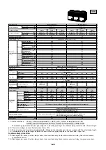
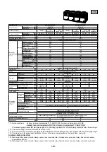
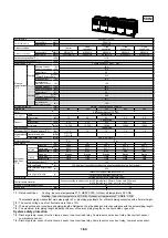
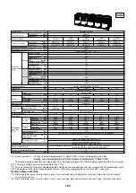
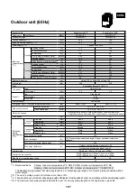
Equivalent HP

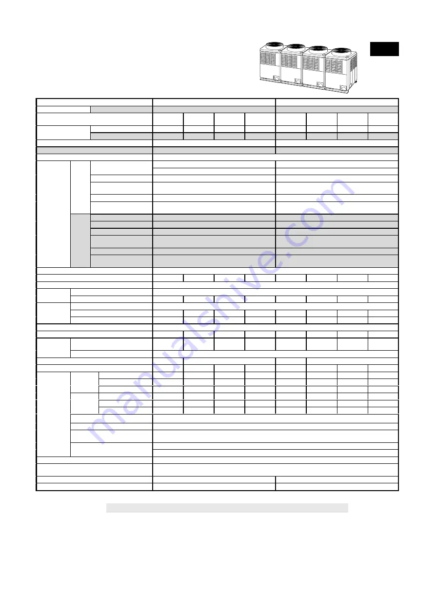
Equivalent to 38HP

Equivalent to 40HP

Set Model name

Heat Pump

MMY-

P3801HT7

P4001HT7

Outdoor unit type

Inverter

Fixed

speed type

Fixed

speed type

Fixed

speed type

Inverter

Fixed

speed type

Fixed

speed type

Fixed

speed type

Cooling Only

MMY-

MP1001T7

MP10017

MP10017

MP08017

MP1001T7

MP10017

MP10017

MP10017

Outdoor unit model

Heat Pump

MMY- MP1001HT7

MP1001H7

MP1001H7

MP0801H7

MP1001HT7

MP1001H7

MP1001H7

MP1001H7

Rated cooling capacity (

*

 1)

(kW)

106.4

112.4

Standard heating capacity (

*

 1)

(kW)

122.5

126.0

Power supply (

*

 2)

3 phase 60Hz 380V

Running current

(A)

79.5

82.8

Power consumption

(kW)

47.2

48.8

Power factor

(%)

86

85

EER                          (kW/kW)
(Energy Efficiency Ratio)

2.25

2.30

Starting current

(A)

21.4

21.4

Cooling

Instantaneous
maximum current

(A)

162

165

Running current

(A)

78.6

82.1

Power consumption

(kW)

46.6

48.6

Power factor

(%)

86

85

EER                          (kW/kW)
(Energy Efficiency Ratio)

2.63

2.59

Starting current

(A)

21.1

21.1

Electrical
characteristics
(

*

 1)

Heating

Instantaneous
maximum current

(A)

178

182

External dimension

(mm)

Height 1,700 x Width 990 x Depth 750

Total weight

(kg)

270

260

260

255

270

260

260

260

Color

Silky shade (Munsell 1Y8.5/0.5)

Type

Hermetic type

Compressor

Motor output

(kW)

7.5

7.5

7.5

6.0

7.5

7.5

7.5

7.5

Fan

Propeller fan

Motor output

(kW)

0.35

0.35

0.35

0.35

0.35

0.35

0.35

0.35

Fan unit

Air volume

(m³/h)

10,000

10,000

10,000

10,000

10,000

10,000

10,000

10,000

Heat exchanger

Finned tube

Refrigerant R407C Charged amount (

*

 3)

(kg)

17.0

9.0

9.0

7.0

17.0

9.0

9.0

9.0

Inverter driving side

(MPa)

OFF : 3.2
ON : 2.55

OFF : 3.2
ON : 2.55

High-pressure
switch

Fixed-speed side

(MPa)

OFF : 2.55, ON : 3.2

Protective devices

(

*

 5)

(

*

 6)

(

*

 5)

(

*

 6)

Case heater

(W)

74

74

74

74

74

74

Gas side

(mm)

Ø28.6

Ø28.6

Ø28.6

Ø25.4

Ø28.6

Ø28.6

Ø28.6

Ø28.6

Liquid side

(mm)

Ø12.7

Ø12.7

Ø12.7

Ø12.7

Ø12.7

Ø12.7

Ø12.7

Ø12.7

Connecting
port dia.

Balance side

(mm)

Ø9.5

Ø9.5

Ø9.5

Ø9.5

Ø9.5

Ø9.5

Ø9.5

Ø9.5

Gas side

Brazing

Brazing

Brazing

Brazing

Brazing

Brazing

Brazing

Brazing

Liquid side

Flare

Flare

Flare

Flare

Flare

Flare

Flare

Flare

Connecting
method

Balance side

Flare

Flare

Flare

Flare

Flare

Flare

Flare

Flare

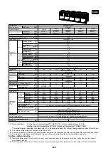
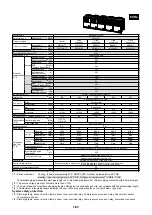
Max. equivalent length

(m)

125

Max. real length

(m)

100 (However, if equivalent bend length is longer, equivalent length is the standard.)

Max. total pipe length
(Real length)

(m)

250

Outdoor unit is higher than indoor unit : 50

Refrigerant
pipe spec.
(

*

 4)

Max. height difference

(m)

Outdoor unit is lower than indoor unit : 30

Control wiring

Shield wire 1.25mm² x 2 cores. up to 500m

Central remote controller

When connecting to outdoor unit : 

MVVS (Shield wire) 1.25mm² x 2 cores up to 500m, and
MVVS (Shield wire) 2.0mm² x 2 cores up to 1000m

Max. No. of connected indoor units

38

40

Sound level

(dB)

63

63

60Hz

*

1 : Rated conditions

Cooling : Indoor air temperature 27°C DB/19°C WB,  Outdoor air temperature 35°C DB
Heating : Indoor air temperature 20°C DB,  Outdoor air temperature 7°C DB/6°C WB

The standard piping measns that main pipe length is 3 m, branching pipe length 2 m of branch piping connected with a 0 meter height.

*

2 : The source voltage must not fluctuate more than ±10%.

*

3 : The amount does not consider extra piping lengths. Refrigerant must be added on site in accordance with the actual piping length.

*

4 : The maximum total piping length indicates the sum of one-way piping lengths on the liquid side or gas side.

System safety protection

*

5 : Discharge temp. sensor, Suction temp. sensor, Inner overload relay, Compressor over-current relay, Over-current sensor,

Low pressure sensor.

*

6 : Discharge temp. sensor, Suction temp. sensor, Inner overload relay, Compressor over-current relay, Low pressure sensor.

Summary of Contents for MMC-P0151H

Page 1: ...ure Type MMD P0181H P0241H P0361H MMD P0481H P0721H P0961H Under Ceiling Type MMC P0151H P0181H P0241H MMC P0361H P0481H High Wall Type MMK P0091H P0121H P0151H MMK P0181H P0241H Floor Standing Cabinet Type MML P0091H P0151H P0181H MML P0241H Floor Standing Concealed Type MML P0091BH P0151BH MML P0181BH P0241BH DESIGN MANUAL FILE NO A02 007 Outdoor Unit Cooling Only Model Inverter Unit MMY MP0801T...

Page 2: ...s to be installed requires a design that in the event of refrigerant gas leaking out its concentration will not exceed a set limit The refrigerant R407C which is used in the air conditioner is safe without the toxicity or combustibility of ammonia and is not restricted by laws to be imposed which protect the ozone layer However since it contains more than air it poses the risk of suffocation if it...

Page 3: ...T PIPING DESIGN 1 19 1 6 WIRING DESIGN 1 22 1 7 CONTROLS 1 28 1 8 ACCESSORIES 1 32 1 9 TECHNICAL SPECIFICATIONS 1 33 1 10 FAN CHARACTERISTICS 1 67 1 11 DIMENSIONAL DRAWINGS 1 69 This Manual is used for both models Cooling Only model and Heat Pump model Positions shaded with screens in the description and tables are applied to the Heat Pump model only Parts marked with XXX indicate the 60Hz 380V mo...

Page 4: ...lly so humidity and temperature are kept in the comfort zone Conforms to building control law IAQ Indoor Air Quality is also achieved by combining various accessories required by the Building Control Law Wide control applications Artificial Intelligence Network system Central control and monitoring system available Weekly schedule operation through weekly timer Integration with Building Management...

Page 5: ...o capacity code of outdoor unit 4 Max 6 0 capacity code in total can be connected 5 If capacity code of outdoor unit is 26 and more it is not used for 1st branching 6 Model names for outdoor and indoor units described in this guide are shortened because of the space constraint 2 Outdoor units Combination of outdoor units 3 Branching joints and headers Corresponding HP 8 HP 10 HP 14 HP 16 HP 18 HP ...

Page 6: ...36 P3601T8 4 MP1001T8 1 MP08018 2 MP10018 1 38HP 38 P3801T8 4 MP1001T8 1 MP08018 1 MP10018 2 40HP 40 P4001T8 4 MP1001T8 1 MP10018 3 42HP 42 P4201T8 5 MP1001T8 1 MP08018 4 44HP 44 P4401T8 5 MP1001T8 1 MP08018 3 MP10018 1 46HP 46 P4601T8 5 MP1001T8 1 MP08018 2 MP10018 2 Cooling Only model 2 Range of combined capacity No of combined units 1 to 5 units Capacity of combined units 14 HP 140 type to 46 H...

Page 7: ...HP 42 P4201HT8 5 MP1001HT8 1 MP0801H8 4 44HP 44 P4401HT8 5 MP1001HT8 1 MP0801H8 3 MP1001H8 1 46HP 46 P4601HT8 5 MP1001HT8 1 MP0801H8 2 MP1001H8 2 Heat Pump model 50Hz 1 Allocation standard of model name 2 Range of combined capacity No of combined units 1 to 5 units Capacity of combined units 14 HP 140 type to 46 HP 460 type 3 Restriction for combination of units 1 The inverter unit should have the...

Page 8: ...42HP 42 P4201HT7 5 MP1001HT7 1 MP0801H7 4 44HP 44 P4401HT7 5 MP1001HT7 1 MP0801H7 3 MP1001H7 1 46HP 46 P4601HT7 5 MP1001HT7 1 MP0801H7 2 MP1001H7 2 MMY M P T 7 H Power supply specifications 3Ø 380 V 60Hz 7 T Capacity variable unit No mark Fixed speed unit H Heat pump Development series No Capacity rank HP x 10 New refrigerant R407C M Single module unit No mark Combined Model name Modular Multi Hea...

Page 9: ...018 type 024 type 036 type 048 type 072 type 096 type 015 type 018 type 024 type 036 type 048 type 009 type 012 type 015 type 018 type 024 type 009 type 015 type 018 type 024 type 009 type 015 type 018 type 024 type Capacity code 1 25 1 7 2 2 5 3 2 4 5 0 8 1 1 25 1 7 2 2 5 3 2 4 5 1 1 25 1 7 2 2 5 0 8 1 1 25 1 7 2 2 5 3 2 4 5 2 2 5 4 5 8 10 1 7 2 2 5 4 5 1 1 25 1 7 2 2 5 1 1 7 2 2 5 1 1 7 2 2 5 Co...

Page 10: ...art Stop Changing mode Temperature setting Air flow changing Timer function Q Either ON time or OFF time can be set how many hours later ON or OFF is operated R Combined with the weekly timer weekly schedule operation can be operated Filter sign Displays automatically maintenance time of indoor filter Filter sign flashes Self diagnosis function Pressing CHK button displays cause of trouble on the ...

Page 11: ...le operation Q Setting different start stop time for each day of the week R ON OFF can be easily set 2 times a day Weekly timer RBC EXW1PE Central remote controller TCB SC641E Individual control up to 64 groups units The controller has the same function as the main remote controller and it can control and display the operation condition for each circuit Integrated setup function The controller can...

Page 12: ...r the branch 0 8 0 8 1 6 Capacity code Indoor unit designation 007 0 8 007 0 8 007 0 8 007 0 8 007 0 8 007 0 8 007 0 8 007 0 8 Indoor unit 6 4 12 8 5 6 4 8 4 0 3 2 2 4 1 6 6 4 5 6 4 8 4 0 3 2 2 4 1 6 Remote controller 007 0 8 007 0 8 007 0 8 007 0 8 007 0 8 007 0 8 007 0 8 007 0 8 10HP Outdoor unit 16 5 26 75 10 25 8 25 10 6 25 5 0 3 75 2 5 8 25 6 25 5 0 3 75 2 5 8 25 6 25 5 0 3 75 2 5 018 2 0 018...

Page 13: ... 009 1 009 1 009 1 012 1 25 012 1 25 012 1 25 024 2 5 036 4 009 1 009 1 009 1 012 1 25 012 1 25 012 1 25 024 2 5 036 4 10HP 10HP 10HP 10HP Outdoor unit 10 20 30 Indoor unit 29 05 45 35 61 9 Remote controller 16 55 15 75 14 5 13 25 12 25 11 25 9 25 007 0 8 012 1 25 012 1 25 009 1 0 009 1 0 018 2 7 25 5 25 018 2 018 2 012 1 25 036 4 16 3 15 5 14 25 13 25 12 25 11 25 9 25 007 0 8 012 1 25 009 1 0 009...

Page 14: ...Y P1801T8 MMY P1801HT8 MMY P1801HT7 18 18 9 to 24 3 MMY P2001T8 MMY P2001HT8 MMY P2001HT7 20 20 10 to 27 MMY P2201T8 MMY P2201HT8 MMY P2201HT7 22 22 11 to 29 7 MMY P2401T8 MMY P2401HT8 MMY P2401HT7 24 24 12 to 32 4 MMY P2601T8 MMY P2601HT8 MMY P2601HT7 26 26 13 to 35 1 MMY P2801T8 MMY P2801HT8 MMY P2801HT7 28 28 14 to 37 8 MMY P3001T8 MMY P3001HT8 MMY P3001HT7 30 30 15 to 40 5 MMY P3201T8 MMY P320...

Page 15: ...c H ho Largest one of ha hb and hc A ha hb hc ho l o l a l b l c B C Air flow variation ratio Indoor units total capacity ratio 5 Correction of outdoor unit diversity 0 80 60 40 20 20 40 60 80 100 120 135 Correction 120 100 Standard capacity ratio Outdoor unit Indoor unit L is the longest one of l o l a l o l b l o l c H ho Largest one of ha hb and hc A ha hb hc ho l o l a l b l c B C Indoor units...

Page 16: ...oor air wet bulb temp C Continuously operable range Usable range in pull down 20 15 10 5 0 5 10 15 20 5 10 15 20 25 30 Continuously operable range Usable range in warming up 4 Capacity calculation for each indoor unit Capacity for each indoor unit Capacity after correction of outdoor unit x Required standard capacity of indoor unit Total value of standard indoor unit capacity 5 Operating temperatu...

Page 17: ...HP Same capacity 2F Outdoor capacity matches the potential total indoor capacity in consideration of future extension The office rooms 2 and 3 are to be used as warehouses at first so air conditioner is not necessary now However there is a plan to convert them into offices so an outdoor module with bigger capacity is required Piping wiring are carried out Indoor unit is not yet installed When the ...

Page 18: ...ng Heating Cooling Heating Judgment 4 1 6 5 6 9 4 2 5 2 5 4 4 3 5 2 5 4 4 4 3 3 3 5 4F 4 5 6 5 6 9 3F 3 1 12 9 13 8 2 1 5 2 5 4 2 2 5 2 5 4 2F 2 3 1 1 6 5 6 9 1 2 6 5 6 9 1 3 8 3 8 6 1F 1 4 43 12 0 920 x 1 0 x 1 0 0 920 0 957 x 1 0 x 0 95 x 0 95 0 864 5 2 5 4 Good Procedure and result of equipment selection 1 Procedure of equipment selection a Calculate cooling for every rooms b Select an indoor u...

Page 19: ...rofile Since the five rooms on the 4th floor face different directions their hourly cooling load profile will be also different We select each indoor unit based on the individual room peak load However we need to use the total load profile on the 4th floor as a base to choose the outdoor module Load in each room Total load in all rooms of 4th floor 1 The total load on the 4th floor is calcu lated ...

Page 20: ...U P0181H R Indoor unit MMU P0301H R Indoor unit MMU P0241H R Indoor unit MMU P0241H Indoor unit MMU P0181H Indoor unit MMU P0181H Indoor unit MMU P0121H Indoor unit MMU P0241H 2 2 2 3 1 1 1 2 1 3 1 4 3rd branching joint 1st branching joint 2nd branching joint 4th branching joint 3rd branching joint 2nd branching joint 4th branching joint 5th branching joint Branching header No Air Conditioner R Sc...

Page 21: ...ee branching system Q Line branching system R Header branching system S Header branching system after line branching T Line branching system after header branching U Header branching system after header branching The above five branching systems are available to dramatically increase the flexibility of refrigerant piping design Line branching system Header branching system Header branching system ...

Page 22: ...r units H1 Lower outdoor unit 30 m Height between indoor units H2 30 m Height difference Height between outdoor units H3 4 m NOTE In case of connecting method Ex 2 a large amount of refrigerant and refrigerant oil may return to the inverter unit Therefore set the T shape joint so that oil does not enter directly Outdoor unit T shape branching joint La LA LB Lb Lc Main piping L1 1st branching secti...

Page 23: ...oor units exceeds that of outdoor units apply the capacity code of outdoor units U Piping of indoor unit Table 5 Capacity rank Gas side 5 Liquid side 007 type to 015 type Ø12 7 Ø 6 4 018 type to 030 type Ø15 9 Ø 9 5 036 type to 048 type Ø19 0 Ø 9 5 072 type Ø25 4 Ø12 7 096 type Ø28 6 Ø12 7 V Selection of branching section Table 6 Total capacity code of indoor unit 1 Model name Below 6 4 RBM BY52E ...

Page 24: ...2 min is recommended to prevent interference 4 Be sure to set the earth leakage breaker and the switches to the power supply section of the indoor unit 5 Supply power to each outdoor unit via a dedicated branch circuit and provide an earth leakage breaker and hand switch for each outdoor unit Outdoor units require Class D grounding Outdoor units use a 3 phase 50Hz 380 400 415V or 60Hz 380V power s...

Page 25: ...her run them through separate conduits or maintain a suitable distance between them Current capacity of power wires 10A or less for 300m 50A or less for 500m 4 Design of control wiring Wire specification quantity size of crossover wire transmission wire and remote controller wire 1 The interconnecting wiring and the central remote controller wiring Optional use 2 core non polar transmission wires ...

Page 26: ...0 67 0 838 15 MMD P0241BH 230 1 50 198 264 0 100 0 70 0 875 15 MMD P0301BH 230 1 50 198 264 0 100 0 85 1 063 15 MMD P0361BH 230 1 50 198 264 0 120 1 26 1 575 15 Concealed Duct Type MMD P0481BH 230 1 50 198 264 0 140 1 26 1 575 15 MMD P0181H 230 1 50 198 264 0 160 0 81 1 013 15 MMD P0241H 230 1 50 198 264 0 160 1 35 1 688 15 MMD P0361H 230 1 50 198 264 0 260 1 63 2 038 15 MMD P0481H 230 1 50 198 26...

Page 27: ...0 15 MMD P0181BH 220 1 60 198 242 0 060 0 70 0 880 15 MMD P0241BH 220 1 60 198 242 0 100 0 82 1 030 15 MMD P0301BH 220 1 60 198 242 0 100 0 95 1 190 15 MMD P0361BH 220 1 60 198 242 0 120 1 37 1 710 15 Concealed Duct Type MMD P0481BH 220 1 60 198 242 0 140 1 37 1 710 15 MMD P0181H 220 1 60 198 242 0 160 0 92 1 150 15 MMD P0241H 220 1 60 198 242 0 160 1 80 2 250 15 MMD P0361H 220 1 60 198 242 0 260 ...

Page 28: ... 65 12 7 12 7 65 12 7 12 7 65 No 2 RLA LRA 12 7 65 11 0 11 0 65 11 0 11 0 65 12 7 12 7 65 11 0 11 0 65 11 0 11 0 65 11 0 11 0 65 12 7 12 7 65 12 7 12 7 65 11 0 11 0 65 11 0 11 0 65 12 7 12 7 65 12 7 12 7 65 12 7 12 7 65 11 0 11 0 65 12 7 12 7 65 12 7 12 7 65 No 3 RLA LRA 12 7 65 11 0 11 0 65 11 0 11 0 65 11 0 11 0 65 12 7 12 7 65 11 0 11 0 65 11 0 11 0 65 11 0 11 0 65 12 7 12 7 65 12 7 12 7 65 11 ...

Page 29: ...80 3 60 380 3 60 380 3 60 380 3 60 380 3 60 380 3 60 380 3 60 380 3 60 380 3 60 380 3 60 380 3 60 380 3 60 380 3 60 380 3 60 380 3 60 380 3 60 Voltage Range Min Max 342 418 342 418 342 418 342 418 342 418 342 418 342 418 342 418 342 418 342 418 342 418 342 418 342 418 342 418 342 418 342 418 342 418 Compressor No 1 RLA LRA 11 5 11 5 77 11 5 11 5 77 13 1 13 1 77 13 1 13 1 77 11 5 11 5 77 11 5 11 5 ...

Page 30: ...2 2 Centralized control of 64 groups A maximum of 1 024 indoor units in 64 different groups can be controlled from a central location 2 3 Weekly timer controller The central remote controller can be connected to a weekly timer to set a weekly running schedule 2 4 Control without indoor remote controller The units can be operated from the central remote controller only without the use of indoor rem...

Page 31: ...ller with timer RBC AT1E Weekly timer RBC EXW1PE Indoor unit Possible up to 500m VSF 0 3 or 0 75mm Remote controller Max 16 units Indoor unit Indoor unit Remote controller Possible up to Max total length 500m VSF 0 3 or 0 75mm Indoor unit Possible up to Max total length l 500m Remote controller Remote controller Group control is also available Indoor unit Remote controller Weekly timer function Se...

Page 32: ...ral management controller for 64 groups Group control of Max 64 groups x 16 units 1 024 units one circuit can have Max 16 units Central remote controller TCB SC641E Weekly timer RBC EXW1PE Indoor remote controller Main remote controller RBC AM1E or Sub remote controller RBC AS1E Central remote controller Weekly timer Weekly operation schedule can be set by connecting a weekly timer to the central ...

Page 33: ...t Single phase 220 230 240V Power supply X Y P Q X Y P Q X Y P Q Single phase 220 230 240V Power supply Single phase 220 230 240V Power supply 1 1 1 2 1 3 2 3 Outdoor unit Central remote controller Central remote controller Indoor remote controller is required Group 1 1 1 2 1 3 2 3 Outdoor unit Central remote controller Group However when grouping operation is performed by connecting multiple indo...

Page 34: ...el RBC UW136PG MMU P0071WH to MMU P0121WH RBC UW266PG MMU P0151WH to MMU P0301WH 2 way Air Discharge Cassette Type Ceiling panel with auto louver RBC UW466PG MMU P0361WH to MMU P0481WH RBC UY135PG MMU P0091SH to MMU P0121SH RBC US165PG MMU P0151SH to MMU P0181SH 1 way Air Discharge Cassette Type Ceiling panel with auto louver RBC US265PG MMU P0241SH TCB TD350P W E MMD P0071BH to MMD P0121BH TCB TD...

Page 35: ...ation Fan Turbo fan Standard air flow High Mid Low m h 720 500 350 1 020 740 520 1 020 740 520 1 200 940 560 1 320 990 600 1 860 1 540 1 080 1 920 1 580 1 160 Fan unit Motor W 60 90 Air filter Long life attached to ceiling panel Controller Remote controller Gas side mm Ø12 7 Ø15 9 Ø19 0 Liquid side mm Ø6 4 Ø9 5 Connecting pipe Drain port Nominal dia 25 Polyvinyl chloride tube Sound level Note 2 Hi...

Page 36: ...lusive for indoor is required Running current A 0 40 0 50 0 55 0 70 1 06 Power consumption kW 0 081 0 103 0 115 0 150 0 230 Power factor 88 90 91 93 94 Electrical characteristics Starting current A 0 6 0 8 1 1 1 2 2 0 Main unit Heat insulating material attached Zinc hot dipping steel plate Model RBC UW136PG RBC UW266PG RBC UW466PG Appearance Ceiling panel Panel color W Silky shade 1Y8 5 0 5 Height...

Page 37: ...al fan Standard air flow High Mid Low m h 540 480 420 780 720 660 1 200 1 140 1 020 Fan unit Motor W 22 34 Controller Remote controller Room thermostat Attached Air filter Attached to ceiling panel Gas side mm Ø12 7 Ø15 9 Liquid side mm Ø6 4 Ø9 5 Connecting pipe Drain port Nominal dia 25 Polyvinyl chloride tube Sound level Note 2 High Mid Low dB A 42 39 34 43 40 36 45 41 37 1 way Air Discharge Cas...

Page 38: ...40 570 490 400 840 740 645 1 140 1 050 950 1 320 1 230 1 150 1 680 1 420 1 210 2 040 1 770 1 550 Motor W 60 100 120 140 External static pressure factory setting Pa 39 2 4 mmAq Fan unit External static pressure Pa 98 10 mmAq Air filter Field supply Controller Remote controller Gas side mm Ø12 7 Ø15 9 Ø19 0 Liquid side mm Ø6 4 Ø9 5 Connecting pipe Drain port Nominal dia 25 Polyvinyl chloride tube So...

Page 39: ...sive for indoor is required Running current A 0 48 0 55 1 06 Power consumption kW 0 103 0 115 0 230 Power factor 93 91 94 Electrical characteristics Starting current A 0 8 1 1 2 0 Appearance Silky shade 1Y8 5 0 5 Outer dimension Height x Width x Depth mm 188 x 1 030 x 640 188 x 1 230 x 640 240 x 1 430 x 640 240 x 1 630 x 640 Total weight kg 24 28 39 44 Heat exchanger Finned tube Soundproof Heat in...

Page 40: ...sive for indoor is required Running current A 0 28 0 48 0 55 Power consumption kW 0 061 0 103 0 115 Power factor 95 93 91 Electrical characteristics Starting current A 0 6 0 8 1 1 Appearance Silky shade 1Y8 5 0 5 Outer dimension Height x Width x Depth mm 630 x 950 x 230 Total weight kg 37 40 Heat exchanger Finned tube Soundproof Heat insulating material Non flammable insulation Fan Centrifugal fan...

Page 41: ...oller Remote controller Part sold separately Gas side mm Ø12 7 Ø15 9 Liquid side mm Ø6 4 Ø9 5 Connecting pipe Drain port Nominal dia 20 One side of male screw Sound level Note 2 High Mid Low dB A 36 34 32 42 37 33 Floor Standing Concealed Type TENTATIVE Note 1 The cooling capacities and electrical characteristics are measured under the conditions speciied by JIS B 8616 based on the reference pipin...

Page 42: ...20 1 200 940 560 1 320 990 600 1 860 1 540 1 080 1 920 1 580 1 160 Fan unit Motor W 60 90 Air filter Long life attached to ceiling panel Controller Remote controller Gas side mm Ø12 7 Ø15 9 Ø19 0 Liquid side mm Ø6 4 Ø9 5 Connecting pipe Drain port Nominal dia 25 Polyvinyl chloride tube Sound level Note 2 High Mid Low dB A 33 31 28 34 31 28 35 32 28 37 33 30 39 36 33 42 38 34 Indoor unit 60Hz speci...

Page 43: ... insulation Fan Centrifugal fan Standard air flow High Mid Low m h 570 510 450 780 700 600 980 780 690 1260 1140 960 1860 1460 1020 1920 1500 1050 Fan unit Motor W 75 120 Air filter Long life attached to ceiling panel Long life attached Controller Remote controller Gas side mm Ø12 7 Ø15 9 Ø19 0 Liquid side mm Ø6 4 Ø9 5 Connecting pipe Drain port Nominal dia 25 Polyvinyl chloride tube Sound level N...

Page 44: ...n Standard air flow High Mid Low m h 540 480 420 780 720 660 1 200 1 140 1 020 Fan unit Motor W 22 34 Controller Remote controller Room thermostat Attached Air filter Attached to ceiling panel Gas side mm Ø12 7 Ø15 9 Liquid side mm Ø6 4 Ø9 5 Connecting pipe Drain port Nominal dia 25 Polyvinyl chloride tube Sound level Note 2 High Mid Low dB A 42 39 34 43 40 36 45 41 37 1 way Air Discharge Cassette...

Page 45: ... 740 645 1 140 1 050 950 1 320 1 230 1 150 1 680 1 420 1 210 2 040 1 770 1 550 Motor W 60 100 120 140 External static pressure factory setting Pa 39 2 4 mmAq Fan unit External static pressure Pa 98 10 mmAq Air filter Field supply Controller Remote controller Gas side mm Ø12 7 Ø15 9 Ø19 0 Liquid side mm Ø6 4 Ø9 5 Connecting pipe Drain port Nominal dia 25 Polyvinyl chloride tube Sound level Note 2 H...

Page 46: ...current A 0 54 0 61 1 22 Power consumption kW 0 116 0 132 0 264 Power factor 98 98 98 Electrical characteristics Starting current A 0 8 1 1 2 0 Appearance Silky shade 1Y8 5 0 5 Outer dimension Height x Width x Depth mm 188 x 1 030 x 640 188 x 1 230 x 640 240 x 1 430 x 640 240 x 1 630 x 640 Total weight kg 24 28 39 44 Heat exchanger Finned tube Soundproof Heat insulating material Non flammable insu...

Page 47: ...ndoor is required Running current A 0 35 0 54 0 61 Power consumption kW 0 075 0 114 0 132 Power factor 97 96 98 Electrical characteristics Starting current A 0 6 0 8 1 1 Appearance Silky shade 1Y8 5 0 5 Outer dimension Height x Width x Depth mm 630 x 950 x 230 Total weight kg 37 40 Heat exchanger Finned tube Soundproof Heat insulating material Non flammable insulation Fan Centrifugal fan Standard ...

Page 48: ...ontroller Remote controller Part sold separately Gas side mm Ø12 7 Ø15 9 Liquid side mm Ø6 4 Ø9 5 Connecting pipe Drain port Nominal dia 20 One side of male screw Sound level Note 2 High Mid Low dB A 36 34 32 42 37 33 Floor Standing ConcealedType TENTATIVE 60Hz Note 1 The cooling capacities and electrical characteristics are measured under the conditions speciied by JIS B 8616 based on the referen...

Page 49: ...relay Compressor over current relay Over current sensor Low pressure sensor Case heater W Gas side mm Ø25 4 Ø28 6 Liquid side mm Ø12 7 Ø12 7 Connecting port dia Balance pipe mm Ø9 5 Ø9 5 Gas side Brazing Brazing Liquid side Flare Flare Connecting method Balance pipe Flare Flare Max equivalent length m 125 Max real length m 100 However if equivalent bend length is longer equivalent length is the st...

Page 50: ...witch Fixed speed side MPa OFF 2 55 ON 3 2 OFF 2 55 ON 3 2 OFF 2 55 ON 3 2 OFF 2 55 ON 3 2 Protective devices 5 6 5 6 5 6 5 6 Case heater W 40 74 74 74 Gas side mm Ø25 4 Ø22 2 Ø25 4 Ø25 4 Ø28 6 Ø25 4 Ø28 6 Ø28 6 Liquid side mm Ø12 7 Ø9 5 Ø12 7 Ø12 7 Ø12 7 Ø12 7 Ø12 7 Ø12 7 Connecting port dia Balance side mm Ø9 5 Ø9 5 Ø9 5 Ø9 5 Ø9 5 Ø9 5 Ø9 5 Ø9 5 Gas side Brazing Brazing Brazing Brazing Brazing B...

Page 51: ...22 2 Ø25 4 Ø25 4 Ø25 4 Liquid side mm Ø12 7 Ø12 7 Ø9 5 Ø12 7 Ø12 7 Ø12 7 Connecting port dia Balance side mm Ø9 5 Ø9 5 Ø9 5 Ø9 5 Ø9 5 Ø9 5 Gas side Brazing Brazing Brazing Brazing Brazing Brazing Liquid side Flare Flare Flare Flare Flare Flare Connecting method Balance side Flare Flare Flare Flare Flare Flare Max equivalent length m 125 Max real length m 100 However if equivalent bend length is lo...

Page 52: ...4 Ø25 4 Ø28 6 Ø28 6 Ø25 4 Liquid side mm Ø12 7 Ø12 7 Ø12 7 Ø12 7 Ø12 7 Ø12 7 Connecting port dia Balance side mm Ø9 5 Ø9 5 Ø9 5 Ø9 5 Ø9 5 Ø9 5 Gas side Brazing Brazing Brazing Brazing Brazing Brazing Liquid side Flare Flare Flare Flare Flare Flare Connecting method Balance side Flare Flare Flare Flare Flare Flare Max equivalent length m 125 Max real length m 100 However if equivalent bend length i...

Page 53: ...m Ø28 6 Ø28 6 Ø28 6 Ø25 4 Ø25 4 Ø25 4 Ø25 4 Liquid side mm Ø12 7 Ø12 7 Ø12 7 Ø12 7 Ø12 7 Ø12 7 Ø12 7 Connecting port dia Balance side mm Ø9 5 Ø9 5 Ø9 5 Ø9 5 Ø9 5 Ø9 5 Ø9 5 Gas side Brazing Brazing Brazing Brazing Brazing Brazing Brazing Liquid side Flare Flare Flare Flare Flare Flare Flare Connecting method Balance side Flare Flare Flare Flare Flare Flare Flare Max equivalent length m 125 Max real...

Page 54: ...e heater W 74 74 74 74 74 74 Gas side mm Ø28 6 Ø25 4 Ø25 4 Ø25 4 Ø28 6 Ø28 6 Ø25 4 Ø25 4 Liquid side mm Ø12 7 Ø12 7 Ø12 7 Ø12 7 Ø12 7 Ø12 7 Ø12 7 Ø12 7 Connecting port dia Balance side mm Ø9 5 Ø9 5 Ø9 5 Ø9 5 Ø9 5 Ø9 5 Ø9 5 Ø9 5 Gas side Brazing Brazing Brazing Brazing Brazing Brazing Brazing Brazing Liquid side Flare Flare Flare Flare Flare Flare Flare Flare Connecting method Balance side Flare Fl...

Page 55: ...74 74 Gas side mm Ø28 6 Ø28 6 Ø28 6 Ø25 4 Ø28 6 Ø28 6 Ø28 6 Ø28 6 Liquid side mm Ø12 7 Ø12 7 Ø12 7 Ø12 7 Ø12 7 Ø12 7 Ø12 7 Ø12 7 Connecting port dia Balance side mm Ø9 5 Ø9 5 Ø9 5 Ø9 5 Ø9 5 Ø9 5 Ø9 5 Ø9 5 Gas side Brazing Brazing Brazing Brazing Brazing Brazing Brazing Brazing Liquid side Flare Flare Flare Flare Flare Flare Flare Flare Connecting method Balance side Flare Flare Flare Flare Flare F...

Page 56: ... Connecting port dia Balance side mm Ø9 5 Ø9 5 Ø9 5 Ø9 5 Ø9 5 Gas side Brazing Brazing Brazing Brazing Brazing Liquid side Flare Flare Flare Flare Flare Connecting method Balance side Flare Flare Flare Flare Flare Max equivalent length m 125 Max real length m 100 However if equivalent bend length is longer equivalent length is the standard Max total pipe length Real length m 250 Outdoor unit is hi...

Page 57: ... 7 Connecting port dia Balance side mm Ø9 5 Ø9 5 Ø9 5 Ø9 5 Ø9 5 Gas side Brazing Brazing Brazing Brazing Brazing Liquid side Flare Flare Flare Flare Flare Connecting method Balance side Flare Flare Flare Flare Flare Max equivalent length m 125 Max real length m 100 However if equivalent bend length is longer equivalent length is the standard Max total pipe length Real length m 250 Outdoor unit is ...

Page 58: ...port dia Balance side mm Ø9 5 Gas side Brazing Liquid side Flare Connecting method Balance side Flare Max equivalent length m 125 Max real length m 100 However if equivalent bend length is longer equivalent length is the standard Max total pipe length Real length m 250 Outdoor unit is higher than indoor unit 50 Refrigerant pipe spec 4 Max height difference m Outdoor unit is lower than indoor unit ...

Page 59: ...current relay Over current sensor Low pressure sensor Case heater W Gas side mm Ø25 4 Ø28 6 Liquid side mm Ø12 7 Ø12 7 Connecting port dia Balance pipe mm Ø9 5 Ø9 5 Gas side Brazing Brazing Liquid side Flare Flare Connecting method Balance pipe Flare Flare Max equivalent length m 125 Max real length m 100 However if equivalent bend length is longer equivalent length is the standard Max total pipe ...

Page 60: ...ch Fixed speed side MPa OFF 2 55 ON 3 2 Protective devices 5 6 5 6 5 6 5 6 Case heater W 40 74 74 74 Gas side mm Ø25 4 Ø22 2 Ø25 4 Ø25 4 Ø28 6 Ø25 4 Ø28 6 Ø28 6 Liquid side mm Ø12 7 Ø9 5 Ø12 7 Ø12 7 Ø12 7 Ø12 7 Ø12 7 Ø12 7 Connecting port dia Balance side mm Ø9 5 Ø9 5 Ø9 5 Ø9 5 Ø9 5 Ø9 5 Ø9 5 Ø9 5 Gas side Brazing Brazing Brazing Brazing Brazing Brazing Brazing Brazing Liquid side Flare Flare Flar...

Page 61: ...5 4 Liquid side mm Ø12 7 Ø12 7 Ø9 5 Ø12 7 Ø12 7 Ø12 7 Connecting port dia Balance side mm Ø9 5 Ø9 5 Ø9 5 Ø9 5 Ø9 5 Ø9 5 Gas side Brazing Brazing Brazing Brazing Brazing Brazing Liquid side Flare Flare Flare Flare Flare Flare Connecting method Balance side Flare Flare Flare Flare Flare Flare Max equivalent length m 125 Max real length m 100 However if equivalent bend length is longer equivalent len...

Page 62: ...25 4 Liquid side mm Ø12 7 Ø12 7 Ø12 7 Ø12 7 Ø12 7 Ø12 7 Connecting port dia Balance side mm Ø9 5 Ø9 5 Ø9 5 Ø9 5 Ø9 5 Ø9 5 Gas side Brazing Brazing Brazing Brazing Brazing Brazing Liquid side Flare Flare Flare Flare Flare Flare Connecting method Balance side Flare Flare Flare Flare Flare Flare Max equivalent length m 125 Max real length m 100 However if equivalent bend length is longer equivalent l...

Page 63: ...Ø25 4 Ø25 4 Ø25 4 Ø25 4 Liquid side mm Ø12 7 Ø12 7 Ø12 7 Ø12 7 Ø12 7 Ø12 7 Ø12 7 Connecting port dia Balance side mm Ø9 5 Ø9 5 Ø9 5 Ø9 5 Ø9 5 Ø9 5 Ø9 5 Gas side Brazing Brazing Brazing Brazing Brazing Brazing Brazing Liquid side Flare Flare Flare Flare Flare Flare Flare Connecting method Balance side Flare Flare Flare Flare Flare Flare Flare Max equivalent length m 125 Max real length m 100 Howeve...

Page 64: ...4 74 74 Gas side mm Ø28 6 Ø25 4 Ø25 4 Ø25 4 Ø28 6 Ø28 6 Ø25 4 Ø25 4 Liquid side mm Ø12 7 Ø12 7 Ø12 7 Ø12 7 Ø12 7 Ø12 7 Ø12 7 Ø12 7 Connecting port dia Balance side mm Ø9 5 Ø9 5 Ø9 5 Ø9 5 Ø9 5 Ø9 5 Ø9 5 Ø9 5 Gas side Brazing Brazing Brazing Brazing Brazing Brazing Brazing Brazing Liquid side Flare Flare Flare Flare Flare Flare Flare Flare Connecting method Balance side Flare Flare Flare Flare Flare...

Page 65: ... 6 Ø28 6 Ø28 6 Ø25 4 Ø28 6 Ø28 6 Ø28 6 Ø28 6 Liquid side mm Ø12 7 Ø12 7 Ø12 7 Ø12 7 Ø12 7 Ø12 7 Ø12 7 Ø12 7 Connecting port dia Balance side mm Ø9 5 Ø9 5 Ø9 5 Ø9 5 Ø9 5 Ø9 5 Ø9 5 Ø9 5 Gas side Brazing Brazing Brazing Brazing Brazing Brazing Brazing Brazing Liquid side Flare Flare Flare Flare Flare Flare Flare Flare Connecting method Balance side Flare Flare Flare Flare Flare Flare Flare Flare Max ...

Page 66: ...dia Balance side mm Ø9 5 Ø9 5 Ø9 5 Ø9 5 Ø9 5 Gas side Brazing Brazing Brazing Brazing Brazing Liquid side Flare Flare Flare Flare Flare Connecting method Balance side Flare Flare Flare Flare Flare Max equivalent length m 125 Max real length m 100 However if equivalent bend length is longer equivalent length is the standard Max total pipe length Real length m 250 Outdoor unit is higher than indoor ...

Page 67: ...t dia Balance side mm Ø9 5 Ø9 5 Ø9 5 Ø9 5 Ø9 5 Gas side Brazing Brazing Brazing Brazing Brazing Liquid side Flare Flare Flare Flare Flare Connecting method Balance side Flare Flare Flare Flare Flare Max equivalent length m 125 Max real length m 100 However if equivalent bend length is longer equivalent length is the standard Max total pipe length Real length m 250 Outdoor unit is higher than indoo...

Page 68: ...side mm Ø9 5 Gas side Brazing Liquid side Flare Connecting method Balance side Flare Max equivalent length m 125 Max real length m 100 However if equivalent bend length is longer equivalent length is the standard Max total pipe length Real length m 250 Outdoor unit is higher than indoor unit 50 Refrigerant pipe spec 4 Max height difference m Outdoor unit is lower than indoor unit 30 Control wiring...

Page 69: ...ter Application lim it Air volume limit Min EH tap H tap M tap L tap Air volume limit Max Long life filter suction panel Long life filter Application lim it Air volume limit Min EH tap H tap M tap L tap Air volume limit Max Long life filter suction panel Long life filter A p p l i c a t i o n l i m i t Air volume limit Min E H t a p H t a p M t a p L t a p Air volume limit Max Long life filter suc...

Page 70: ...ume 1320m h External static pressure Pa 1056 1584 High static pressure tap High static pressure tap Medium static pressure tap Low static pressure tap Low static pressure tap 0 5 294 245 196 147 98 49 0 1 1 5 2 MMD P0481H Current of fan motor A Standard air volume 2100m h External static pressure Pa 1680 2520 700 800 900 1000 1100 Air volume m h 1200 1400 1600 1800 2000 Air volume m h 1000 1100 12...

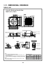
Page 71: ...imension 620 Hanging bolt pitch 820 Unit external dimension 880 Ceiling open dimension 940 Panel external dimension 940 940 800 Hanging bolt pitch Infrared receiver Suction grille Air suction port Air discharge port Up to 4 Ways 227 112 80 185 170 100 60 127 187 Drain pipe connecting port Inner dia Ø32 Vinyl chloride pipe VP25 connected Refrigerant pipe connecting port Liquid side C Refrigerant pi...

Page 72: ...O Wire connecting port Water supply port Drain pipe connecting port Inner dia Ø32 polyvinyl chloride pipe VP25 connected Refrigerant pipe connecting port At gas side P 178 Ø 1 5 0 Knockout hole for fresh air At opposite side only 95 60 35 30 Center of air condition main unit Center of panel Unit external dimension D Panel external dimension A Ceiling open dimension B Hanging bolt pitch C 20 70 Pan...

Page 73: ...al dimension 680 Ceiling open dimension 650 Unit external dimention 620 Electric parts box Hanging bolt pitch 510 348 282 242 78 100 56 75 55 210 15 15 Refrigerant pipe connecting port At liquid side Ø9 52 Wire connecting port Water supply port Drain pipe connecting port Inner dia Ø32 polyvinyl chloride pipe VP25 connected Refrigerant pipe connecting port At gas side Ø19 0 178 Ø 1 5 0 Knockout hol...

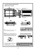
Page 74: ...enter of panel Panel external dimension 1050 Ceiling open dimension 1010 Panel external dimension Ceiling open dimension Discharge louver Support metal Panel mounting hole 5 positions Discharge port Air suction grille Space necessary for installation and servicing Drain pipe connecting port VP25 20 20 50 455 395 110 890 330 400 430 20 20 150 100 85 200 120 225 140 235 18 850 1050 470 400 850 470 1...

Page 75: ...caused 1 When using drain up pipes at a position 500mm or less from the bottom side of the ceiling use a polyvinyl chloride tube of 1 by cutting 2 For horizontal piping use the attached polyvinyl chloride tube Extension of pipe is unavailable at site Ø150 Knockout hole For taking in fresh air When take in fresh air attach a filter etc so that fresh air does not enter directly Y view Power connecti...

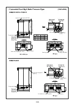
Page 76: ...5 Unit external dimension 800 25 170 321 210 26 90 120 70 Refrigerant pipe connectting port Gas side F 210 Hanging bolt pitch 565 25 720 509 300 315 240 25 L Inside dimension Z 240 160 Inside dimension 6x4mm screw holes at 160mm diameter Ø125 Knockout hole for Flesh air intake 80 130 100 Z View 65 65 65 65 65 65 65 65 65 65 65 Detail of flange for air intake duct L I D 240 25 12 5 I D 12 5 25 S Ø5...

Page 77: ... Electric parts box Power source Connecting wire port Ø26 Electric parts box lower side Refrigerant pipe connecting port Liquid side B Refrigerant pipe connecting port Liquid side Ø9 5 Refrigerant pipe connecting port Gas side A Refrigerant pipe connecting port Gas side Ø19 0 Long hole for hanging bolt 4 Ø12 72 Drain pipe connecting port VP25 Drain pipe connecting port VP25 Z View Discharge port S...

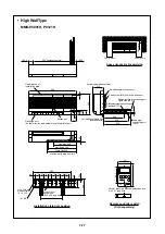
Page 78: ...Both sides Refrigerant pipe connecting port Gas side G Refrigerant pipe connecting port Liquid side F 400 or more 150 or more 150 or more 500 or more From left Drain pipe connecting port VP25 Bolt hole for mounting 4 12 27 long hole From right Drain pipe connecting port VP25 Knockout hole for piping wiring Hanging bolt pitch Hanging bolt pitch Hanging metal Left Accessory Hanging metal Right Acces...

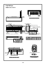
Page 79: ...nt pipe connecting port Liquid side Ø6 4 Drain pipe connecting port VP20 Discharge port Air flow direction is adjustable to up down left right Suction port Left and Right piping port Knockout hole Space necessary for servicing At shipment Piping from left Liquid pipe 540 Drain pipe 560 Gas pipe 440 300 or more 300 or more 30 or more Hole for mounting wall and embedded box 2 4 5 x 7 long hole 102 5...

Page 80: ...Including installation plate Installation plate Accessory Earth screw M4 In electric oarts box Drain pipe connecting port VP20 Discharge port Air flow direction is adjustable to up down left right Suction port At shipment Piping from left Liquid pipe 540 Drain pipe 560 Gas pipe 440 690 Installation plate Refrigerant pipe connecting port Liquid side L Refrigerant pipe connecting port Gas side K Hol...

Page 81: ...ain pipe connecting port VP20 Discharge port Air flow direction is adjustable to up down left right At shipment Piping from left Liquid pipe 540 Drain pipe 560 Gas pipe 440 1090 Installation plate Refrigerant pipe connecting port Liquid side Ø9 5 Refrigerant pipe connecting port Gas side Ø15 9 Remote controller switch Sold separately Space necessary for servicing 300 or more 300 or more 30 or more...

Page 82: ...ut pulsometor hole x 2 Operation switch box Wall fixing hole 2 10 24 long hole Lower refrigerant piping port 50 100 knockout hole Floor fixing hole 2 Ø10 500 or more 1000or more 200 or more Drain pipe connecting port VP20 Refrigerant pipe connecting port Gas side A Refrigerant pipe connecting port Liquid side B wall wall Space for installation and servicing Right piping in figure Refrigerant pipin...

Page 83: ...late Discharge port flange inner dimension Floor fixing hole Discharge port flange inner dimension 2 12 18 long hole Floor fixing hole No Name 1 2 3 4 5 Pipe connecting port at liquid side E Pipe connecting port at gas side F Drain pipe connecting port VP20 Electric parts box Earth terminal is mounted inside Air filter 135 Dimensions mm Model A B C D E F G MML P0241BH MML P0181BH MML P0151BH MML P...

Page 84: ... hole Base bolt position 755 Anchor bolt pitch 790 Including fixed leg 2 60 150 Square hole For treating forklift load Anchor bolt pitch Balance pipe connecting port 500 1700 1560 700 90 88 115 145 140 170 125 64 20 65 35 55 125 173 610 100 700 750 100 630 80 755 28 80 245 D 190 Model MMY MP10018 MP1001T8 MP08018 MP0801T8 MP06018 MP1001H8 MP1001HT8 MP1001H7 MP1001HT7 MP0801H8 MP0801HT8 MP0801H7 MP...

Page 85: ...20mm or more 8 15 20 Long hole Including fixed leg Rear side Front side 1550mm or more 500mm or more 300mm or more 10mm or more 10mm or more 20mm or more 2020mm or more 700 Anchor bolt pitch 990 990 700 Anchor bolt pitch 755 Anchor bolt pitch 750 790 1700 1560 700 90 88 1 2 310 No Name 1 2 Outdoor Unit Inverter type Outdoor Unit Fixed speed type ...

Page 86: ...ong hole Including fixed leg Rear side Front side 1550mm or more 500mm or more 300mm or more 10mm or more 10mm or more 20mm or more 20mm or more 3030mm or more 700 Anchor bolt pitch 990 990 990 700 Anchor bolt pitch 700 Anchor bolt pitch 755 Anchor bolt pitch 750 790 1700 1560 700 90 88 1 2 3 310 310 No Name 1 2 3 Outdoor Unit Inverter type Outdoor Unit Fixed speed type 1 Outdoor Unit Fixed speed ...

Page 87: ...ore 16 15 x 20 Long hole 990 700 Anchor bolt pitch 990 700 Anchor bolt pitch 990 700 Anchor bolt pitch 755 Anchor bolt pitch 750 790 Including fixed leg 1 2 3 4 20mm or more 20mm or more 20mm or more 10mm or more 10mm or more 300mm or more Rear side Front side 500mm or more 4040mm or more 1550mm or more 310 310 310 No Name 1 2 3 4 Outdoor Unit Inverter type Outdoor Unit Fixed speed type 1 Outdoor ...

Page 88: ...d speed type 4 20mm or more 990 5030 1700 1560 700 90 88 700 Anchor bolt pitch 20mm or more 20mm or more 990 700 Anchor bolt pitch 990 700 Anchor bolt pitch 990 700 Anchor bolt pitch 1 2 3 4 20mm or more 20 15 x 20 Long hole 990 700 Anchor bolt pitch 750 755 Anchor bolt pitch 790 Including fixed leg 5 20mm or more 20mm or more 20mm or more 10mm or more 10mm or more 300mm or more Rear side Front si...

Page 89: ...5 8 24 Ø12 7 10 36 Ø19 0 Ø9 5 9 39 Ø19 0 1 7 10 13 4 piece Outer dia 1 piece Outer dia 1 piece Outer dia 1 piece Outer dia Ø28 6 22 64 80 80 384 80 50 86 6 Ø19 Ø12 7 10 36 Ø19 0 Ø15 9 12 50 Ø28 6 Ø19 0 16 52 Ø28 6 Ø25 4 20 48 Ø28 6 Ø15 9 12 33 Ø19 0 10 13 16 20 24 4 piece Outer dia 4 piece Outer dia 1 piece Outer dia 1 piece Outer dia 1 piece Outer dia ...

Page 90: ... Ø9 5 8 24 Ø12 7 10 36 Ø19 0 9 39 Ø19 0 1 7 10 13 8 piece Outer dia 1 piece Outer dia 1 piece Outer dia 1 piece Outer dia Ø28 6 22 704 80 80 80 80 80 80 80 68 50 86 6 Ø19 Ø12 7 10 36 Ø19 0 Ø19 0 16 52 Ø28 6 Ø25 4 20 48 Ø28 6 Ø15 9 12 33 Ø19 0 10 13 20 24 8 piece Outer dia 6 piece Outer dia 1 piece Outer dia 1 piece Outer dia ...

Page 91: ...2 33 Ø19 0 Ø6 4 Ø9 5 8 24 Ø12 7 10 36 Ø19 0 Ø9 5 9 39 Ø19 0 1 7 10 13 4 piece Outer dia 1 piece Outer dia 1 piece Outer dia 1 piece Outer dia Ø38 1 26 68 389 80 80 80 50 92 3 Ø19 Ø12 7 10 36 Ø19 0 Ø31 8 23 58 Ø38 1 Ø15 9 12 33 Ø19 0 10 13 24 2 piece Outer dia 4 piece Outer dia 1 piece Outer dia ...

Page 92: ...0 Ø6 4 Ø9 5 Ø9 5 8 24 Ø12 7 10 36 Ø19 0 9 39 Ø19 0 1 7 10 13 8 piece Outer dia 1 piece Outer dia 1 piece Outer dia 1 piece Outer dia Ø38 1 26 709 80 80 80 80 80 80 80 68 50 92 3 Ø19 Ø12 7 10 36 Ø19 0 Ø31 8 23 58 Ø38 1 Ø15 9 12 33 Ø19 0 10 13 28 8 piece Outer dia 8 piece Outer dia 1 piece Outer dia Gas side ...

Page 93: ... 1 9 9 Ø9 5 Ø9 5 65 Ø9 5 9 200 2 piece Outer dia Ø9 5 9 32 Ø15 9 6 12 Ø15 9 Ø15 9 80 12 Ø19 0 15 250 Ø12 7 10 28 Ø15 9 Ø15 9 Ø19 0 Ø15 9 12 16 33 38 Ø19 0 9 13 51 52 Ø22 2 Ø19 0 18 43 2 piece Outer dia 2 piece Outer dia 1 piece Outer dia 1 piece Outer dia 1 piece Outer dia ...

Page 94: ... 7 12 31 Outer dia 5 54 10 Ø12 7 Ø12 7 80 Ø12 7 10 250 10 1 piece 11 20 20 Ø25 4 Ø25 4 80 Ø28 6 22 350 Ø12 7 10 46 Ø25 4 Outer dia 2 piece 2 piece Ø15 9 12 46 Ø25 4 Outer dia Ø19 0 Ø31 8 Ø28 6 16 23 46 55 Ø25 4 Outer dia 1 piece Outer dia 15 19 2 piece Ø22 2 18 44 Ø25 4 Outer dia 1 piece Ø25 4 20 48 Ø28 6 Outer dia 22 24 53 ...

Page 95: ... dia 1 piece Outer dia 2 piece Outer dia 1 piece Outer dia 1 piece Outer dia 22 22 Ø31 8 Ø31 8 80 Ø38 1 26 350 12 Ø12 7 10 55 Ø31 8 Ø15 9 12 54 Ø31 8 Ø19 0 16 55 Ø31 8 17 21 Ø25 4 20 53 Ø31 8 25 Ø31 8 Ø31 8 26 64 Ø28 6 22 23 49 Ø31 8 Ø31 8 58 Ø38 1 27 28 55 1 piece Outer dia 1 piece Outer dia 1 piece Outer dia 2 piece Outer dia 1 piece Outer dia 1 piece Outer dia 2 piece Outer dia ...

Page 96: ... dia 2 piece Outer dia 2 piece Outer dia 1 piece Outer dia 1 piece Outer dia 29 Ø44 5 Ø44 5 110 Ø44 5 29 26 Ø25 4 400 20 71 Ø31 8 23 69 Ø44 5 Ø44 5 Ø38 1 26 63 Ø44 5 Ø28 6 22 70 Ø44 5 29 Ø19 0 16 70 Ø44 5 Ø50 8 33 80 Ø44 5 32 33 30 34 42 56 29 Ø15 9 12 68 Ø44 5 Ø12 7 10 67 Ø44 5 2 piece Outer dia 2 piece Outer dia 3 piece Outer dia 1 piece Outer dia 1 piece Outer dia 1 piece Outer dia 1 piece Oute...

Page 97: ...10 46 Ø15 9 Ø25 4 12 46 15 74 19 19 19 Ø25 4 37 Ø25 4 Ø25 4 42 11 11 11 Ø15 9 23 Ø15 9 Ø15 9 2 piece Outer dia 1 piece Outer dia 35 Ø38 1 26 73 Ø28 6 22 77 Ø50 8 Ø50 8 37 31 Ø50 8 126 Ø50 8 31 31 Ø50 8 61 26 Ø38 1 102 Ø38 1 26 26 Ø38 1 51 2 piece Outer dia 4 piece Outer dia ...

Page 98: ...TOSHIBA CARRIER CORPORATION 336 TADEHARA FUJI SHI SHIZUOKA KEN 416 8521 JAPAN ...

Reviews: