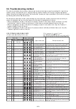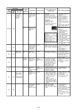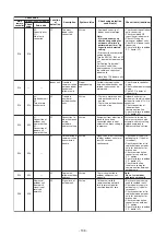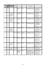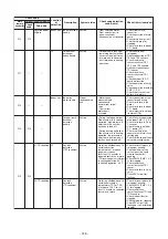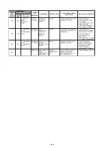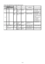
Check code
Location
of
detection
Description
System status
Check code detection
condition(s)
Check items (locations)
• Check check code
displayed on outdoor
follower unit.
<Convenient functions>
If SW04 is pressed and held
for at least 1 second while
[E28] is displayed on the 7-
segment display of outdoor
header unit, the fan of the
outdoor unit that has been
shut down due to an trouble
comes on.
If SW04 and SW05 are
pressed simultaneously, the
fans of normal outdoor units
come on.
To stop the fan or fans,
press SW05 on its own.
I/F
Detected
outdoor unit No.
Outdoor
follower unit
trouble
All stop
Outdoor header unit
receives trouble code from
outdoor follower unit.
E28
E28
• Check wiring and
connectors involved in
communication between
P.C. board I/F P.C. board for
bad contact or broken wire.
• Check for failure in outdoor
P.C. board (I/F, comp. P.C.
board or Fan P.C. board).
• Check for external noise.
I/F
Circle (O):
Trouble
P.C. board
P.C. board
communication
trouble
All stop
Communication is disrupted
between P.C. board in
inverter box.
E31
E31
• Operation of power supply
reset (OFF for 60 seconds
or more)
• Outdoor I/F PC board
trouble check
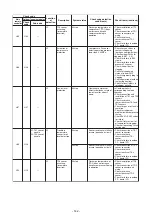
Communication
trouble between
MCU and Sub
MCU
All stop
Communication between
MCU and Sub MCU
stopped.
80
• Check connection of TCJ
sensor connector and
wiring.
• Check resistance
characteristics of TCJ
sensor.
• Check for failure in indoor
P.C. board.
Indoor TCJ
sensor trouble
Indoor unit
Stop of
corresponding
unit
Sensor resistance is infinity
or zero (open/short circuit).
F01
—
—
• Check connection of TC2
sensor connector and
wiring.
• Check resistance
characteristics of TC2
sensor.
• Check for failure in indoor
P.C. board.
Indoor TC2
sensor trouble
Indoor unit
Stop of
corresponding
unit
Sensor resistance is infinity
or zero (open/short circuit).
F02
—
—
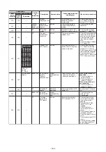
• Check connection of TC1
sensor connector and
wiring.
• Check resistance
characteristics of TC1
sensor.
• Check for failure in indoor
P.C. board.
Indoor TC1
sensor trouble
Indoor unit
Stop of
corresponding
unit
Sensor resistance is infinity
or zero (open/short circuit).
F03
—
—
• Check connection of TD1
sensor connector.
• Check resistance
characteristics of TD1
sensor.
• Check for failure in outdoor
P.C. board (I/F).
TD1 sensor
trouble
I/F
All stop
Sensor resistance is infinity
or zero (open/short circuit).
F04
F04
—
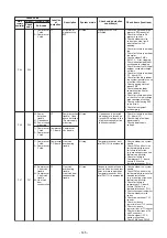
Main
remote
controller
Outdoor 7-segment display
Check
code
Sub-code
P.C.board
Compressor Fan Motor
01
02
03
08
09
0A
0B
10
O
O
O
O
O
O
O
O
O
O
O
O
O
1
2
1
2
11
12
13
18
19
1A
1B
O
O
O
O
O
O
O
O
O
O
O
O
O
O
O
- 139 -
Summary of Contents for MMC-UP0151HP-E
Page 41: ...2 2 Ceiling type MMC UP0151HP E TR MMC UP0181HP E TR 41 ...
Page 42: ...MMC UP0241HP E TR MMC UP0271HP E TR 6 4 12 7 42 ...
Page 43: ...MMC UP0361HP E TR MMC UP0481HP E TR MMC UP0561HP E TR 43 ...
Page 58: ...3 WIRING DIAGRAMS 3 1 4 way cassette type MMU UP HP E TR 58 ...
Page 59: ...3 2 Ceiling type MMC UP HP E TR 59 ...
Page 60: ...3 3 Concealed Duct Standard type MMD UP BHP E TR 60 ...
Page 61: ...3 4 Concealed Duct High Static Pressure type MMD UP HP E TR 61 ...
Page 62: ...Concealed Duct High Static Pressure type MMD UP HP E TR 62 ...
Page 63: ...3 5 Concealed Duct High Static Pressure fresh air intake type MMD UP HFP E TR 63 ...
Page 65: ...3 7 High wall type MMK UP HP E TR 65 ...
Page 249: ...MMU UP0361HP E TR MMU UP0481HP E TR MMU UP0561HP E TR 268 267 213 214 249 ...
Page 252: ...12 2 Ceiling type MMC UP0151HP E TR MMC UP0181HP E TR 025 024 252 ...
Page 254: ...MMC UP0241HP E TR MMC UP0271HP E TR 029 028 254 ...
Page 256: ...MMC UP0361HP E TR MMC UP0481HP E TR MMC UP0561HP E TR 051 028 027 256 ...
Page 261: ...MMD UP0151BHP E TR MMD UP0181BHP E TR 240 239 238 233 235 261 ...
Page 263: ...MMD UP0241BHP E TR MMD UP0271BHP E TR MMD UP0301BHP E TR 240 239 238 233 235 263 ...
Page 265: ...MMD UP0361BHP E TR MMD UP0481BHP E TR MMD UP0561BHP E TR 240 239 238 233 235 265 ...

