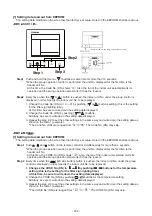
[3] Writing the setting data to EEPROM
The settings stored in the EEPROM of the P.C. board for indoor unit servicing are the factory-set values.
<RBC-ASCU11-
>
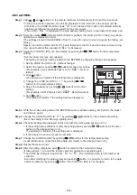
Step 1
Push and hold the [menu +
] buttons at same time for more than 10 seconds.
* When the group operation control is performed, the unit No. displayed for the first time is the
header unit No.
At this time, the Code No. (DN) shows “10”. Also, the fan of the indoor unit selected starts its
operation and the swing operation also starts if it has the louvers.
Step 2
Every time when the [
or
] button is pushed, the indoor unit No. in the group control operation
are displayed in order.
(The settings stored in the EEPROM of the P.C. board for indoor unit servicing are the factory-set
values.)
Specify the indoor unit No. with its P.C. board replaced to the P.C. board for indoor unit servicing.
(You cannot perform this operation if “ALL” is displayed.)
Step 3
Select the Code No. (DN) can be selected by pushing the [
or
] button.
• Set the indoor unit type and capacity.
The factory-set values shall be written to the EEPROM by changing the type and capacity.
1. Push the [menu] button to make Code No. flash. And set the Code No. (DN) to10 .
2. Push the [menu] button to make SET DATA flash. And select the type by pushing the [•¤ or •¢]
buttons.
(For example, 4-way Cassette Type is set to “0001”. Refer to table 2)
3. Push [OFF timer] button.
(The changed data is set.)
4. Change the Code No. (DN) to”11” by pushing the [
or
] buttons.
5. Select the capacity by pushing the [
or
] buttons.
(For example, UP009 Type is set to “0003”. Refer to table 3)
6. Push [OFF timer] button.
(The changed data is set.)
Step 4
Write the on-site setting data to the EEPROM, such as address setting, etc. Perform the steps 1
and 2 above again.
Step 5
Change the Code No. (DN) to “01” by pushing the [
or
] buttons.
(this is the setting for the filter sign lighting time.)
Step 6
Check the setting data displayed at this time with the setting data put down in [1].
1. If the setting data is different, modify the setting data by pushing the [
or
] buttons to the
data put down in [1].
2. If the data is the same, proceed to next step.
Step 7
Change the Code No. (DN) by pushing the [
or
] buttons.
As described above, check the setting data and modify to the data put down in [1].
Step 8
Repeat the steps 6 and 7.
Step 9
After the setting completes, push the [ON/OFF] button to return to the normal stop status.
(It takes approx. 1 min until the remote controller operation is available again.)
- 165 -
Summary of Contents for MMC-UP0151HP-E
Page 41: ...2 2 Ceiling type MMC UP0151HP E TR MMC UP0181HP E TR 41 ...
Page 42: ...MMC UP0241HP E TR MMC UP0271HP E TR 6 4 12 7 42 ...
Page 43: ...MMC UP0361HP E TR MMC UP0481HP E TR MMC UP0561HP E TR 43 ...
Page 58: ...3 WIRING DIAGRAMS 3 1 4 way cassette type MMU UP HP E TR 58 ...
Page 59: ...3 2 Ceiling type MMC UP HP E TR 59 ...
Page 60: ...3 3 Concealed Duct Standard type MMD UP BHP E TR 60 ...
Page 61: ...3 4 Concealed Duct High Static Pressure type MMD UP HP E TR 61 ...
Page 62: ...Concealed Duct High Static Pressure type MMD UP HP E TR 62 ...
Page 63: ...3 5 Concealed Duct High Static Pressure fresh air intake type MMD UP HFP E TR 63 ...
Page 65: ...3 7 High wall type MMK UP HP E TR 65 ...
Page 249: ...MMU UP0361HP E TR MMU UP0481HP E TR MMU UP0561HP E TR 268 267 213 214 249 ...
Page 252: ...12 2 Ceiling type MMC UP0151HP E TR MMC UP0181HP E TR 025 024 252 ...
Page 254: ...MMC UP0241HP E TR MMC UP0271HP E TR 029 028 254 ...
Page 256: ...MMC UP0361HP E TR MMC UP0481HP E TR MMC UP0561HP E TR 051 028 027 256 ...
Page 261: ...MMD UP0151BHP E TR MMD UP0181BHP E TR 240 239 238 233 235 261 ...
Page 263: ...MMD UP0241BHP E TR MMD UP0271BHP E TR MMD UP0301BHP E TR 240 239 238 233 235 263 ...
Page 265: ...MMD UP0361BHP E TR MMD UP0481BHP E TR MMD UP0561BHP E TR 240 239 238 233 235 265 ...


