No.
Part to be replaced
Work procedure
Remarks
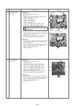
⑩
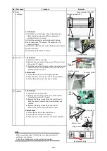
Heat exchanger
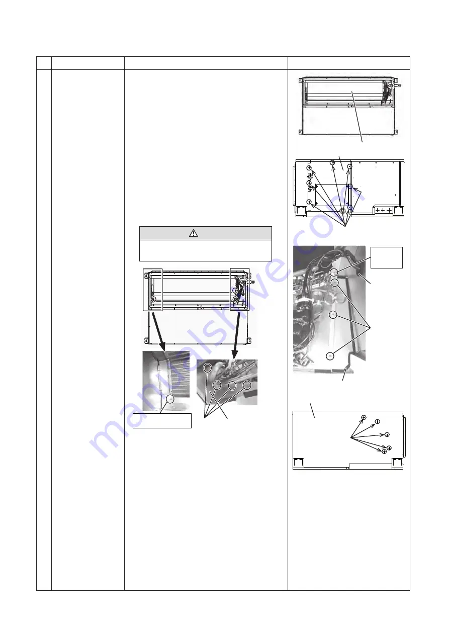
1. Detachment
1) Recover the refrigerant gas, and remove the
refrigerant pipe connection of the indoor unit.
2) Remove the drain plate. (see the 1. Of No.
⑧
)
3) Remove the screws A (7 pcs), and remove the side
plate (left). (Screws locate under the cross slit on the
heat-insulating material)
4) Remove the electric parts box cover. Remove the
TC1 / TC2 / TCJ sensor connectors from the board,
and pull out the sensor from the bushing to the heat
exchanger side.
5) Remove the screws B (3 pcs), and remove the heat
exchanger partition plate (rear).
6) Remove the screws C (4 pcs), and remove the heat
exchanger partition plate (bottom).
7) Remove the screws D (5 pcs) to secure the heat
exchanger and the side plate (right). (Screws locate
under the cross slit on the heat-insulating material)
8) While supporting the heat exchanger, remove the
screws E (2 pcs) and then slowly remove the heat
exchanger.
Caution
Be sure that the work is performed by two
persons or more with great care.
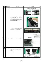
Screw E
(side plate (right) side)
Screw C
Heat exchanger
partition plate
(bottom)
2. Attachment
1) Mount the heat exchanger in the same position as
before replacement.
(Screw E (2 pcs))
2) Secure the heat exchanger to the side plate (right).
(Screw D (5 pcs))
3) Reinstall the heat exchanger partition plate (bottom) in
the same way as before replacement.
(Screw C (4 pcs))
4) Reinstall the heat exchanger partition plate (rear) in
the same way as before replacement.
(Screw B (3 pcs))
5) Re-connect the TC sensor in the same way as before
replacement.
(see the 1), 3), 4) under 2. of No.
⑨
)
6) Reinstall the side plate (left) in the same way as before
replacement. (Screw A (7 pcs))
7) Attach the drain pan. (see the 2. of No,
⑧
)
Heat exchanger
Side plate (left)
Screw A
Screw E
(side plate
(left) side)
Bushing
Heat exchanger partition plate (rear)
Side plate (right)
Screw D
Screw B
- 220 -
Summary of Contents for MMC-UP0151HP-E
Page 41: ...2 2 Ceiling type MMC UP0151HP E TR MMC UP0181HP E TR 41 ...
Page 42: ...MMC UP0241HP E TR MMC UP0271HP E TR 6 4 12 7 42 ...
Page 43: ...MMC UP0361HP E TR MMC UP0481HP E TR MMC UP0561HP E TR 43 ...
Page 58: ...3 WIRING DIAGRAMS 3 1 4 way cassette type MMU UP HP E TR 58 ...
Page 59: ...3 2 Ceiling type MMC UP HP E TR 59 ...
Page 60: ...3 3 Concealed Duct Standard type MMD UP BHP E TR 60 ...
Page 61: ...3 4 Concealed Duct High Static Pressure type MMD UP HP E TR 61 ...
Page 62: ...Concealed Duct High Static Pressure type MMD UP HP E TR 62 ...
Page 63: ...3 5 Concealed Duct High Static Pressure fresh air intake type MMD UP HFP E TR 63 ...
Page 65: ...3 7 High wall type MMK UP HP E TR 65 ...
Page 249: ...MMU UP0361HP E TR MMU UP0481HP E TR MMU UP0561HP E TR 268 267 213 214 249 ...
Page 252: ...12 2 Ceiling type MMC UP0151HP E TR MMC UP0181HP E TR 025 024 252 ...
Page 254: ...MMC UP0241HP E TR MMC UP0271HP E TR 029 028 254 ...
Page 256: ...MMC UP0361HP E TR MMC UP0481HP E TR MMC UP0561HP E TR 051 028 027 256 ...
Page 261: ...MMD UP0151BHP E TR MMD UP0181BHP E TR 240 239 238 233 235 261 ...
Page 263: ...MMD UP0241BHP E TR MMD UP0271BHP E TR MMD UP0301BHP E TR 240 239 238 233 235 263 ...
Page 265: ...MMD UP0361BHP E TR MMD UP0481BHP E TR MMD UP0561BHP E TR 240 239 238 233 235 265 ...


