No.
19
Item
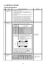
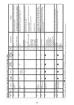
Louver control
(Continued)
Outline of specifications
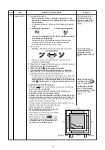
• If there is the locked louver in the unit, [
] goes on the
remote controller screen.
• While the following controls are performed, the louvers
operate even if executing the louver lock.
Remarks
For the setting operation,
refer to [How to set louver
lock] of Installation Manual.
• The real louver corresponding to the louver No. displayed
on the remote controller screen during setting of louver
lock operates swinging.
Control which ignores lock
Operation stop
When heating operation started
Heating thermostat OFF
During defrost operation
Initialize operation
Objective louver No.
Full-close position
Horizontal discharge position
Horizontal discharge position
Horizontal discharge position
Full-close position
It is position check operation
and it does not link with the
real louver and air direction
setup (Illustration on the
remote controller screen).
20
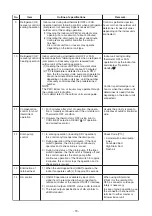
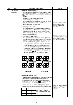
DC motor
1) When the fan starts, positioning is performed for the
starter and the rotor. (Vibrate slightly)
2) DC motor operates according to the command from
the indoor controller.
(Note)
If the fan rotates by entry of outside air, etc while
the air conditioner stopped, the indoor unit may
operate as the fan motor stops.
(Note)
If the fan lock was detected, the operation of the
indoor unit stops and the check code is displayed.
Chec
Subject model :
Compact 4-way
2-way cassette
1-way cassette (SH)
Floor standing
k code [P12]
21
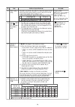
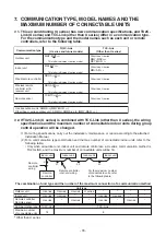
Power saving
mode
1.
2.
3.
4.
(In the case of RBC-AMT
∗∗∗
)
Push the
button on the remote controller
The “ ” segment lights up on the wired remote
controller display.
The requirement capacity ratio is limited to
approximately 75 %.
If the power saving operation is enabled, the settings
are retained when the operation is stopped, when the
mode is changed, or when the power is reset.
The power saving operation will be enabled at the next
time the operation starts.
• The operation may differ depending on the connected
outdoor unit. Refer to the Service Manual of the
outdoor unit.
SAVE
- 77 -
Summary of Contents for MMC-UP0151HP-E
Page 41: ...2 2 Ceiling type MMC UP0151HP E TR MMC UP0181HP E TR 41 ...
Page 42: ...MMC UP0241HP E TR MMC UP0271HP E TR 6 4 12 7 42 ...
Page 43: ...MMC UP0361HP E TR MMC UP0481HP E TR MMC UP0561HP E TR 43 ...
Page 58: ...3 WIRING DIAGRAMS 3 1 4 way cassette type MMU UP HP E TR 58 ...
Page 59: ...3 2 Ceiling type MMC UP HP E TR 59 ...
Page 60: ...3 3 Concealed Duct Standard type MMD UP BHP E TR 60 ...
Page 61: ...3 4 Concealed Duct High Static Pressure type MMD UP HP E TR 61 ...
Page 62: ...Concealed Duct High Static Pressure type MMD UP HP E TR 62 ...
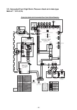
Page 63: ...3 5 Concealed Duct High Static Pressure fresh air intake type MMD UP HFP E TR 63 ...
Page 65: ...3 7 High wall type MMK UP HP E TR 65 ...
Page 249: ...MMU UP0361HP E TR MMU UP0481HP E TR MMU UP0561HP E TR 268 267 213 214 249 ...
Page 252: ...12 2 Ceiling type MMC UP0151HP E TR MMC UP0181HP E TR 025 024 252 ...
Page 254: ...MMC UP0241HP E TR MMC UP0271HP E TR 029 028 254 ...
Page 256: ...MMC UP0361HP E TR MMC UP0481HP E TR MMC UP0561HP E TR 051 028 027 256 ...
Page 261: ...MMD UP0151BHP E TR MMD UP0181BHP E TR 240 239 238 233 235 261 ...
Page 263: ...MMD UP0241BHP E TR MMD UP0271BHP E TR MMD UP0301BHP E TR 240 239 238 233 235 263 ...
Page 265: ...MMD UP0361BHP E TR MMD UP0481BHP E TR MMD UP0561BHP E TR 240 239 238 233 235 265 ...

