background image

SMMS Slim Duct Type

Installation Manual

EN

SMMS Slim Duct Type

Installation Manual

– 8 –

„

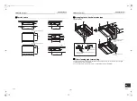
Installation of indoor unit

Treatment of ceiling

The ceiling differs according to structure of building.


For details, consult your constructor or interior finish 
contractor.


In the process after the ceiling board has been 
removed, it is important to reinforce ceiling foundation 
(frame) and to keep horizontal level of installed ceiling 
correctly in order to prevent vibration of ceiling board.


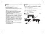
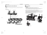
• Attach the nuts and the M10 flat washers to the 

hanging bolt.

• Put washers at up and down of the hanging bracket 

of the indoor unit to hang down the indoor unit.

• Check that four sides are horizontal with a level 

gauge. (Horizontal degree: Within 5 mm)

„

Installation of remote 
controller (Sold separately)

For installation of the wired remote controller, follow the 
Installation Manual attached with the remote controller.
• Pull out the remote controller cord together with the 

refrigerant pipe or drain pipe.


Pass the remote controller cord through upper side 
of the refrigerant pipe and drain pipe.

• Do not leave the remote controller at a place 

exposed to the direct sunlight and near a stove.

„

Wireless remote controller

The sensor of indoor unit with wireless remote 
controller can receive a signal by distance within 
approx. 8 m. Based upon it, determine a place where 
the remote controller is operated and the installation 
place.
• Operate the remote controller, confirm that the 

indoor unit receives a signal surely, and then install 
it.

• Keep 1 m or more from the devices such as 

television, stereo.


(Disturbance of image or noise may generate.)

• To prevent a malfunction, select a place where is not 

influenced by a fluorescent light or direct sunlight.

• Two or more (Up to 6 units) indoor units with wireless 

type remote controller can be installed in the same 
room.

Nut 

(W3/8 or M10)

M10 flat washer

(Accessory)

M10 flat washer

(Accessory)

Hanging bolt 

(W3/8 or M10)

Nut


(W3/8 or M10)

8 m o

r less

5

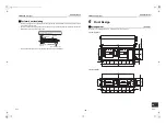
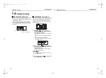
Drain Piping

CAUTION

Following the Installation Manual, perform the drain 
piping work so that water is properly drained, and 
apply a heat insulation so as not to cause a dew 
drop.


Inappropriate piping work may result in water 
leakage in the room and wet of furniture.

„

Piping / Heat insulating material

Require the following materials for piping and heat 
insulating at site.

„

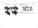
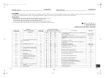
Flexible hose

Use the attached flexible hose to adjust centre 
discrepancy of the hard vinyl chloride pipe or to adjust 
the angle.
• Do not use the flexible hose as stretched, or do not 

deform it more extent than that in the following figure.

• Fix the soft end of the flexible hose with the attached 

hose band.

• Use the flexible hose on a horizontal level.

REQUIREMENT

• Perform heat insulation of the drain pipes of the indoor 

unit.

• Perform heat insulation of the connecting part with the 

indoor unit. 


An incomplete heat insulation causes dew drop.

• Set the drain pipe with downward slope (1/100 or 

more), and do not make swelling or trap on the piping. 
It may cause an abnormal sound.

• For length of the traversing drain pipe, restrict to 20 m 

or less.


To use a long pipe, provide support brackets with 
interval of 1.5 - 2 m in order to prevent waving.

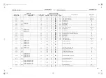
• Set the collective piping as shown in the below figure.

• Do not apply force to the connecting part of the drain 

pipe.

• The hard vinyl-chloride pipe cannot be directly 

connected to the drain pipe connecting port of the 
indoor unit.


For connection with the drain pipe connecting port, fix 
the attached flexible hose with the hose band, 
otherwise a damage or water leak is caused on the 
drain pipe connecting port.

Piping

Hard vinyl chloride pipe VP25 

(Outer dia.: Ø32 mm)

Heat insulator

Foam polyethylene: 


Thickness 10 mm or more

OK

NO GOOD

max

45°

max

45°

90° Bend

Riser (Trap)

Top view

Side view

Side view

Air outlet

Side view

Air outlet

Air outlet

Support 

bracket

1/100 or more 

downward

Heat insulator

1.5 - 2 m

Arched


shape

Trap

NO 

GOOD

VP25

As long as possible (100 mm)

Downward slope 

1/100 or more

VP30 or more

VP25

VP25

15-EN

16-EN

+00EH99879301_01EN.book  Page 8  Tuesday, March 15, 2011  8:42 PM

Summary of Contents for MMD-AP0074SPH-E

Page 1: ...sh Indoor Unit Model name Slim Duct Type MMD AP0074SPH E MMD AP0094SPH E MMD AP0124SPH E MMD AP0154SPH E MMD AP0184SPH E AIR CONDITIONER MULTI TYPE Installation Manual 00EH99879301_01EN book Page 1 Tuesday March 15 2011 8 42 PM ...

Page 2: ... piping work involved in installation relocation and removal has the qualifications pertaining to this refrigerant handling and piping work as stipulated by the local laws and regulations and he or she is a person who has been trained in matters relating to refrigerant handling and piping work on the air conditioners made by Toshiba Carrier Corporation or alternatively he or she has been instructe...

Page 3: ...pair of outdoor unit Gloves to provide protection for electricians and from heat Warning indications on the air conditioner unit Warning indication Description WARNING ELECTRICAL SHOCK HAZARD Disconnect all remote electric power supplies before servicing WARNING Moving parts Do not operate unit with grille removed Stop the unit before the servicing CAUTION High temperature parts You might get burn...

Page 4: ...ance in a place where it is directly exposed to the wind of air conditioner otherwise it may cause imperfect combustion Installation Suction duct length must be longer than 850 mm When the indoor unit is to be suspended the designated hanging bolts M10 or W3 8 and nuts M10 or W3 8 must be used Install the air conditioner securely in a location where the base can sustain the weight adequately If th...

Page 5: ...er It is dangerous for the air conditioner to be relocated by an unqualified individual since a fire electric shocks injury water leakage noise and or vibration may result When carrying out the pump down work shut down the compressor before disconnecting the refrigerant pipe Disconnecting the refrigerant pipe with the service valve left open and the compressor still operating will cause air or oth...

Page 6: ... trouble in the air conditioner or noise may adversely affect the equipment s operation Locations where there is anything under the unit installed that would be compromised by wetness If the drain has become blocked or when the humidity is over 80 condensation from the indoor unit will drip possibly causing damage to anything underneath In the case of the wireless type of system rooms with the inv...

Page 7: ...erm setup of the filter sign Notification of filter cleaning of the remote controller can be changed according to the condition of installation For setup method refer to Filter sign setting in the Applicable controls of this Manual Remove the cover plate and then fix it to the bottom surface Do surely hooking to the main unit Main unit after remover Air filter Main unit Air filter Force Remove the...

Page 8: ... 103 21 20 40 359 372 422 502 19 21 21 163 Ø 9 2 31 Installation of hanging bolt Consider the piping wiring after the unit is hung to determine the location of the indoor unit installation and orientation After the location of the indoor unit installation has been determined install hanging bolts For the dimensions of the hanging bolt pitches refer to the external view When a ceiling already exist...

Page 9: ...10 Nut W3 8 or M10 8 m or less 5 Drain Piping CAUTION Following the Installation Manual perform the drain piping work so that water is properly drained and apply a heat insulation so as not to cause a dew drop Inappropriate piping work may result in water leakage in the room and wet of furniture Piping Heat insulating material Require the following materials for piping and heat insulating at site ...

Page 10: ...e and hose band for connecting the drain hose to the clear drain socket If applying the adhesive socket will be damaged and cause water leakage Align the attached hose band to the end of hose set the tightening position upward and then tighten it Flexible hose Accessory Socket for VP25 vinyl chloride pipe locally procured Drain pipe connecting port Hard socket VP25 vinyl chloride pipe locally proc...

Page 11: ...ts and seams of the heat insulator upward to avoid water leakage Wrap the attached heat insulator seamlessly from the surface of the indoor unit Flexible hose Hose band Attached heat insulator Heat insulator to be procured locally Hard vinyl chloride pipe 6 Duct Design Arrangement Unit mm Referring to the following dimensions manufacture duct at the local site Under air intake Back air intake 805 ...

Page 12: ...lete heat insulation of the supply air flange and sealing may occur dewing resulted in falling of water drop Flange locally procured Aluminum tape locally procured Aluminum tape locally procured Under surface Cover a screw Heat insulator with sticking material 100 mm width locally procured Aluminum tape locally procured Air discharge side Indoor unit Air intake side Connect a duct to the inside of...

Page 13: ...static pressure 20 Pa External static pressure Pa Air Volume m3 h Filter attached AP007 AP009 AP012 AP015 AP018 0 10 20 30 40 50 60 300 400 500 600 700 Standard air volume 540 m3 h Upper limit of external static pressure 50 Pa High 50 Pa Lower limit of externa static pressure 50 Pa Low 50 Pa High 20 Pa Low 35 Pa Low 20 Pa High 10 Pa Low 10 Pa Upper limit of external static pressure 35 Pa Upper lim...

Page 14: ...0 to 1 5 12 7 15 9 Outer dia of copper pipe A 0 0 4 6 4 9 1 9 5 13 2 12 7 16 6 15 9 19 7 Work using double spanner Use the tightening torque levels as listed in the table below Tightening torque of flare pipe connections Pressure of R410A is higher than that of R22 Approx 1 6 times Therefore using a torque wrench tighten the flare pipe connecting sections which connect the indoor and outdoor units...

Page 15: ...e power supply specifications follow to the table below If capacity is little it is dangerous because overheat or burnout may be caused For specifications of the power capacity of the outdoor unit and the power supply wires refer to the Installation Manual attached to the outdoor unit Indoor unit power supply For the power supply of the indoor unit prepare the exclusive power supply separated from...

Page 16: ...Pass the wires through the bushing of wire connection holes of the indoor unit Keep a margin Approx 100 mm on a wire to hang down the electrical control box at servicing or other purpose The low voltage circuit is provided for the remote controller Do not connect the high voltage circuit Before remove the electrical control box cover remove the cover plate and air filter Remove the cover of the el...

Page 17: ...ange the indoor unit settings The settings are changed by operating the wired remote controller The settings cannot be changed using only a wireless remote controller simple remote controller or group control remote controller by itself so install a wired remote controller separately as well Basic procedure for changing settings Change the settings while the air conditioner is not working Stop the...

Page 18: ... 6 Specify 5d to the CODE No in procedure 3 For the SET DATA of procedure 4 select a SET DATA of the external static pressure to be set up from the following table Change on wired remote controller With a remote controller less system group control Besides the switching method using the wired remote controller as a way to establish the external static pressure switching is also possible by changin...

Page 19: ... Detection temperature shift value 0000 No shift 0001 1 C 0002 2 C Factory default 0003 3 C 0004 4 C 0005 5 C 0006 6 C SET DATA 0000 0001 Remotecontroller sensor Not used Factory default Used 10Test Run Before test run Before turning on the power supply carry out the following procedure 1 By using 500 V megger check that resistance of 1 MΩ or more exists between the terminal block L to N and the e...

Page 20: ...n finished stop the air conditioner from the wireless remote controller and return Dip switch of the receiver section as before A 60 minutes timer clearing function is attached to the receiver section in order to prevent a continuous test operation Small screw Nameplate Notch M4 25 screw 2 pieces Spacer Receiver unit 11Maintenance Daily maintenance Cleaning of air filter If is displayed on the rem...

Page 21: ... service person Maintenance List Parts Inspection method Heat exchanger Access from inspection opening and remove the access panel Examine the heat exchanger if there is any clogging or damages Fan motor Access from inspection opening and check if any abnormal noise can be heard Fan Access from inspection opening and remove the access panel Examine the fan if there are any waggles damages or adhes...

Page 22: ...he log can be confirmed from both operating status and stop status 1 When and buttons are pushed simultaneously for 4 seconds or more the following display appears If is displayed the mode enters in the error log mode 01 Order of error log is displayed in CODE No Error code is displayed in CHECK Indoor unit address in which an error occurred is displayed in Unit No 2 Every pushing of button used t...

Page 23: ... E03 97 Communication error between indoor unit and remote controller Detected at indoor unit side Indoor unit E04 04 Communication circuit error between indoor outdoor unit Detected at indoor unit side Indoor unit E06 E06 No of indoor units in which sensor has been normally received 04 Decrease of No of indoor units I F E07 Communication circuit error between indoor outdoor unit Detected at outdo...

Page 24: ...break down IPDU H02 H02 01 Comp 1 side 02 Comp 2 side 03 Comp 3 side 1d Compressor trouble lock IPDU H03 H03 01 Comp 1 side 02 Comp 2 side 03 Comp 3 side 17 Current detect circuit system error IPDU H04 H04 44 Comp 1 case thermo operation I F H05 H05 TD1 sensor miswiring I F H06 H06 20 Low pressure protective operation I F H07 H07 d7 Oil level down detective protection I F H08 H08 01 TK1 sensor err...

Page 25: ...01 Comp 1 side 02 Comp 2 side 03 Comp 3 side AF ALT Phase missing detection Power failure detection Inverter DC voltage error comp Inverter DC voltage error comp Inverter DC voltage error comp I F P07 P07 01 Comp 1 side 02 Comp 2 side 03 Comp 3 side IC ALT Heat sink overheat error IPDU I F P09 P09 Detected heat storage address 47 ALT No heat storage unit water error Heat storage unit P10 P10 Detec...

Page 26: ... Comp 3 Fan Check code Wireless remote controller Check code name Judging device Central control device indication Outdoor unit 7 segment display AI NET central control display Sensor block display of receiving unit Auxiliary code Operation Timer Ready Flash C05 Sending error in TCC LINK central control device TCC LINK C06 Receiving error in TCC LINK central control device TCC LINK C12 Batch alarm...

Page 27: ...United Kingdom Hereby declares that the machinery described below Generic Denomination Air Conditioner Model type MMD AP0074SPH E MMD AP0094SPH E MMD AP0124SPH E MMD AP0154SPH E MMD AP0184SPH E Commercial name Super Modular Multi System Air Conditioner Super Heat Recovery Multi System Air Conditioner Mini Super Modular Multi System Air Conditioner MiNi SMMS series Complies with the provisions of t...

Page 28: ... air conditioners is 0 3 kg m3 NOTE 1 If there are 2 or more refrigerating systems in a single refrigerating device the amounts of refrigerant should be as charged in each independent device For the amount of charge in this example The possible amount of leaked refrigerant gas in rooms A B and C is 10 kg The possible amount of leaked refrigerant gas in rooms D E and F is 15 kg NOTE 2 The standards...

Page 29: ...IGH STATIC 2 0003 F HIGH STATIC 3 0006 External static pressure CODE NO 5d F NO CHANGE F STANDARD 0000 F HIGH STATIC 1 0001 F HIGH STATIC 2 0003 F HIGH STATIC 3 0006 External static pressure CODE NO 5d F NO CHANGE F STANDARD 0000 F HIGH STATIC 1 0001 F HIGH STATIC 2 0003 F HIGH STATIC 3 0006 Have you changed lighting time of filter sign If not fill check mark in NO CHANGE and fill check mark in IT...

Page 30: ...EH99879399 00EH99879301_01EN book Page 33 Tuesday March 15 2011 8 42 PM ...

Reviews: