–
86
–
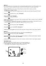
Method 2
If it is not possible to turn on the indoor unit or read the setting data from the P.C. board to be replaced via a
wired remote controller or operate the remote controller due to the failure of its power supply circuit -
Replacing EEPROM (For the location of this component and the method to replace it, see the
“ EEPROM location diagram” section.)
• The EEPROM on the P.C. board to be replaced needs to be removed and mounted on the service P.C. board.
Replacing P.C. board and turning on power:
Procedure 2
Reading EEPROM data:
Procedure 1
• If data cannot be read, go to Method 3.
Replacing EEPROM again (For the location of this component and the method to replace it, see the “EEPROM
location diagram” section.)
• The old EEPROM, supplied with the P.C. board to be replaced and now mounted on the service P.C. board,
needs to be replaced with the new EEPROM, supplied with the service P.C. board.
Replacing P.C. board and turning on power:
Procedure 2
Writing EEPROM data in new EEPROM:
Procedure 3
Resetting power supply (applicable to all indoor units connected to remote controller in case of group operation)
Method 3
If it is not possible to read the setting data due to the failure of the EEPROM itself -
Replacing P.C. board and turning on power:
Procedure 2
Writing EEPROM data on basis of information supplied by customer (e.g. External static pressure selection
setting and optional connection setting):
Procedure 3
Resetting power supply (applicable to all indoor units connected to remote controller in case of group operation)
<EEPROM layout>
EEPROM is attached to IC socket. To remove it, use a pair of tweezers, etc.
To attach EEPROM, arrange the direction as shown in the following figures.
” In exchanging time, pay attention not to bend the lead wire of IC.
J01
CN73
(RED)
T01
IC503
SW501
IC101
C08
C09
1
2
EEPROM
Cut out
EEPROM
Cut out
IC socket


