–
92
–
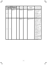
No.
Part name
Procedure
Remarks
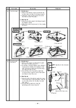
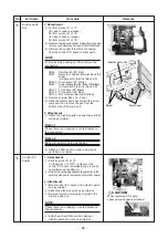
1. Detachment
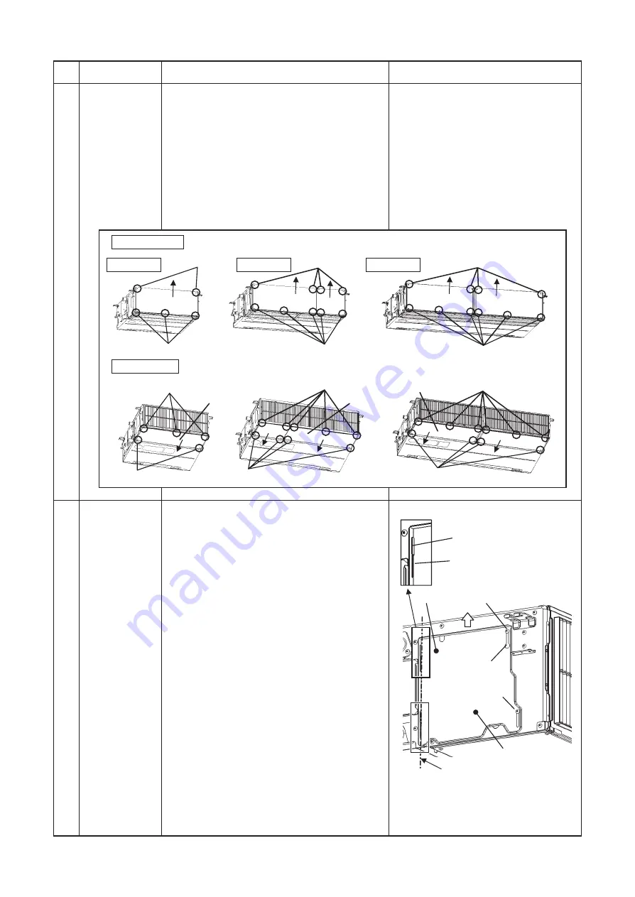
1) Remove the fixing screws A which fix the
suction panel. Loosen the fixing screws B.
2) Slide the suction panel to the arrow side
and then remove the panel.
2. Attachment
1) Hook the suction panel to the fixing screws B
and tighten screws.
2) Attach the removed screws A to the original
positions.
Suction panel
d
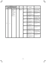
1. Detachment
1) Remove the screw A of the electric parts
box cover to loosen screw B.
2) As shown in the right figure, when sliding it
toward arrow direction and pulling to this
side, the electric parts cover opens using
the hinge part as a shaft.
3) Take off the slit of the electric parts box
cover from the projection of the side plate
and then remove the cover.
2. Attachment
1) Hook the slit of the electric parts box cover
to the projection of the side plate, close the
cover, enter screw B in the Key hole and
then slide it.
2) Fix the electric parts box cover by
tightening with screws A and B.
Electric parts
box cover
e
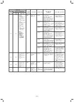
Projection on the side plate
Slit
Side plate
Screw B
Key hole
Screw-A
Hinge part
Electric parts box cover
Under air intake
Back air in
take
AP007 Type
AP024 Type
AP036 Type
Fixing screws A
Fixing screws A
Fixing screws A
Fixing screws A
Fixing screws A
Fixing screws A
Suction panel
Suction panel
Suction panel
Suction panel
Suction panel
Suction panel
Fixing screws B
Fixing screws B
Fixing screws B
Fixing screws B
Fixing screws B
Fixing screws B


