background image

21

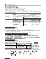
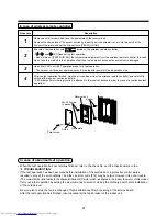
In case of wireless remote controller

Receiver unit

M4 × 25 screw
(2 pieces)

Small screw

Spacer

Notch

Nameplate

In case of abnormal test operation

• When the test operation has not normally finished, refer to the check No. and the check position in the

9  TROUBLESHOOTING”.

• If the test operation has been executed before installation of the outside duct, a protective control works

resulted in stop of the air conditioner, and then an error code [P12] may be output. However it is not a trouble.

(The current limit control works in the characteristics of DC motor which is adopted in the indoor fan motor of this model.)

Carry out a test operation by setting the air volume tap to small or closing the discharge port before installation
of the outside duct.

• Be sure also to stop the fan in exchange of high-performance filter or opening of the service board.

After the test operation has finished, reset necessarily the leak breaker of the indoor unit.

Procedure

1

2

3

4

Description

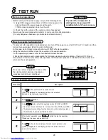
Remove a small screw which fixes the nameplate of the receiver unit.

Remove the nameplate of the sensor section by inserting a minus screwdriver, etc into the notch at the
bottom of the plate, and set the Dip switch to [TEST RUN ON].

Execute a test operation with 

 button on the wireless remote controller.

, and 

 LED flash during test operation.

• Under status of [TEST RUN ON], the temperature adjustment from the wireless remote controller is invalid.

Do not use this method in the operation other than test operation because the equipment is damaged.

Use either COOL or HEAT operation mode for a test operation.

* The outdoor unit does not operate approx. 3 minutes after power-ON and operation stop.

After the test operation finished, stop the air conditioner from the wireless remote controller, and return Dip
switch of the receiver section as before.
(A 60-minutes timer clearing function is attached to the receiver section in order to prevent a continuous test
operation.)

Summary of Contents for MMD- AP0091BH

Page 1: ...R MULTI SYSTEM AIR CONDITIONER For commercial use Not accessible to the general public Indoor Unit Concealed Duct Type MMD AP0071BH AP0091BH AP0121BH MMD AP0151BH AP0181BH AP0241BH MMD AP0271BH AP0301BH AP0361BH MMD AP0481BH AP0561BH ...

Page 2: ...l and hand over it ADOPTION OF NEW REFRIGERANT This Air Conditioner is a new type which adopts a new refrigerant HFC R410A instead of the conventional refrigerant R22 in order to prevent destruction of the ozone layer CONTENTS Accessory parts and Parts to be procured locally 3 1 PRECAUTIONS FOR SAFETY 4 2 SELECTION OF INSTALLATION PLACE 5 3 INSTALLATION OF INDOOR UNIT 7 4 DRAIN PIPING WORK 9 5 REF...

Page 3: ...different from those of the conventional refrigerant Take out the flare nut attached to the indoor unit of the air conditioner and use it Part name Installation Manual Heat insulating pipe Washer Q ty 1 2 8 Shape This manual M10 Ø34 Usage Be sure to hand over to customers For heat insulation of pipe connecting section For hanging up unit Part name Standard wired remote controller Q ty 1 Shape Usag...

Page 4: ...connect the Appliance from Main Power Supply This appliance must be connected to the main power supply by means of a switch with a contact separation of at least 3 mm WARNING Ask an authorized dealer or qualified installation professional to install maintain the air conditioner Inappropriate installation may result in water leakage electric shock or fire Turn off the main power supply switch or br...

Page 5: ...ECTION OF INSTALLATION PLACE WARNING Install the air conditioner at enough strong place to withstand the weight of the unit If the strength is not enough the unit may fall down resulting in injury Install the air conditioner at a height 2 5m or more from the floor If you insert your hands or others directly into the unit while the air conditioner operates it is dangerous because you may contact wi...

Page 6: ...tenance for electric parts such as fan motor is unavailable Reference Dewing test conditions Indoor side 27 C dry bulb temperature 24 C wet bulb temperature Air volume Low air volume operation time 4 hours Installation under high humidity atmosphere In some cases including the rainy season especially inside of the ceiling may become high humidity atmosphere dew point temperature 23 C or higher 1 I...

Page 7: ...ess remote controller can be installed in the same room Within 8m 3 INSTALLATION OF INDOOR UNIT WARNING Install the air conditioner certainly to sufficiently withstand the weight If the strength is insufficient the unit may fall down resulting in human injury Perform a specified installation work to guard against strong wind or earthquake An incomplete installation can cause accidents by the units...

Page 8: ... units central control system wire and remote controller wire up to the position where pipes and wires are connected before hanged up the indoor unit The hanging bolts and nuts will be procured locally Anchor bolt Blade type bracket Slide type bracket Pipe hanging anchor bolt Reinforcing steel Hanging bolt Hanging bolt Support angle Installation of hanging bolt Use M10 hanging bolts 4 pcs to be lo...

Page 9: ...welling or trap on the piping It may cause an abnormal sound For length of the traversing drain pipe restrict to 20m or less In case of a long pipe provide support brackets with interval of 1 5 to 2m in order to prevent waving Set the collective piping as shown in the right figure Do not mount an air purge pipe otherwise drain water spouts out resulted in water leak The hard vinyl chloride pipe ca...

Page 10: ... the float switch connector to the original position CN34 of P C board and then set the electric parts box as before Thermal insulating process After check of draining apply thermal insulation surely to the pipe connecting part Give taping without clearance to the striking section of the main unit with thermal insulator at local site Rising up 550mm or less 100mm or less Indoor unit 220 240V 50Hz ...

Page 11: ...al and dimensions Piping material Model MMD AP Pipe size mm Gas side Liquid side Phosphor deoxidization joint less pipe for air conditioner 0071BH to 0121BH 0151BH to 0181BH 0241BH to 0561BH Ø9 5 Ø12 7 Ø15 9 Ø6 4 Ø6 4 Ø9 5 0 0 4 A Use a clean and new pipe and check that impurity such as dust oil moisture etc does not adhere in the pipe Pipe Forming End Positioning Flaring 1 Cut the pipe with a pip...

Page 12: ...ting sections which connect the indoor and outdoor units of the specified tightening torque Incorrect connections may cause not only a gas leak but also a trouble of the refrigerating cycle REQUIREMENT If an excessive torque is applied the nut may crack depending on the installation conditions Airtight test Air purge etc For airtight test air purge addition of refrigerant and gas leak check follow...

Page 13: ...ing Otherwise the system will be failed Perform the electric wiring so that it does not come to contact with the high temperature part of the pipe The coating may melt resulted in an accident After connecting wires to the terminal blocks provide a trap and fix wires with the wire clamp Store the refrigerant piping line and control wiring line in the same line Do not turn on the power of the indoor...

Page 14: ...g of the remote controller wiring and group remote controllers wiring Remote controller inter unit wiring Indoor unit Remote controller Indoor unit L1 L2 Ln Max 8 units Indoor unit Indoor unit Remote controller wiring Twist wire 0 5mm2 to 2 0mm2 2 Total wire length of remote controller wiring and remote controller inter unit wiring L L1 L2 Ln In case of wired type only In case of wireless type inc...

Page 15: ... The cover of the electric parts box remains hanged to the hinge Tighten the screws of the terminal block and fix the wires with cord clamp attached to the electric parts box Do not apply tension to the connecting section of the terminal block Be sure to set a loop for the connecting wire of the storing part of the indoor unit electric parts otherwise the electric parts box cannot be drawn out in ...

Page 16: ...roller wiring of indoor unit A B Approx 200mm W White B Black W B Remote controller wire Local procure Wire from remote controller unit or sensor Connecting part Remote controller unit or sensor part Wire from remote controller or sensor Remote controller wiring Wire joint Header unit Follower unit Earth leakage breaker Earth leakage breaker Switch Earth Open Earth Outdoor power supply 3 phase 380...

Page 17: ...at the displayed item code is 10 If the item code indicates other than 10 push button to erase the display and then retry the operation from the first step For some time after button has been pushed the operation of the remote controller cannot be accepted In a group control the firstly displayed indoor unit No becomes the center unit The display changes according to the indoor unit model Every pu...

Page 18: ...a Standard At shipment 70Pa 1 High static pressure 1 100Pa 2 High static pressure 2 20Pa High static pressure 1 65Pa for Model AP0481BH AP0561BH 2 90Pa for Model AP0481BH AP0561BH In case of remote controller less Group control For setup to the high ceiling there is selecting method by exchanging the short plugs on the indoor microcomputer P C board as shown in the following table other than selec...

Page 19: ...asic operation procedure 1 2 3 4 5 6 For the item code in Procedure 3 specify 06 For the set data in Procedure 4 select the setup data of shift value of detection temperature to be set up from the table below Setup data 0000 0001 0002 0003 0004 0005 0006 Detection temp shift value No shift 1 C 2 C At shipment from factory 3 C 4 C 5 C 6 C Group control In a group control a remote controller can con...

Page 20: ...owing items 1 Using 500V megger check there is 1MΩ or more between the terminal block of the power supply and the earth If 1MΩ or less is detected do not run the unit 2 Check that all the valves of the outdoor unit are fully opened Never push the electromagnetic contactor to carry out a forced test operation It is very dangerous because a protective device does not work How to execute test operati...

Page 21: ...peration has finished reset necessarily the leak breaker of the indoor unit Procedure 1 2 3 4 Description Remove a small screw which fixes the nameplate of the receiver unit Remove the nameplate of the sensor section by inserting a minus screwdriver etc into the notch at the bottom of the plate and set the Dip switch to TEST RUN ON Execute a test operation with button on the wireless remote contro...

Page 22: ... 1 2 3 Description When pushing SET and buttons simultaneously for 4 seconds or more the right display appears If Service Check is displayed the mode enters in the error history mode 01 Order of error history is displayed in CODE No window Check Code is displayed in CHECK window Indoor unit address in which an error occurred is displayed in UNIT No Every pushing buttons the error history stored in...

Page 23: ...is nothing during automatic addressing Capacity over No of connected indoor units Communication error between indoor units Outdoor header units quantity error Other line connected during automatic address Sending error in communication between outdoor units Duplicated follower outdoor addresses Decrease of No of connected outdoor units Follower outdoor unit error IPDU communication error Judging d...

Page 24: ...me Indoor TCJ sensor error Indoor TC2 sensor error Indoor TC1 sensor error TD1 sensor error TD2 sensor error TE1 sensor error TL sensor error TO sensor error Indoor TA sensor error TS1 sensor error TH sensor error Outdoor temp sensor miscabling TE TL Outdoor pressure sensor miscabling Pd Ps Ps sensor error Pd sensor error Indoor other error Indoor EEPROM error Compressor break down Magnet switch e...

Page 25: ...oor overflow error Indoor fan motor error Outdoor liquid back detection error Gas leak detection Discharge temp TD2 error 4 way valve inverse error High pressure protective operation Outdoor fan IPDU error G TR short protection error Comp position detective circuit system error Other indoor unit error Group terminal unit error Error in indoor group AI NET communication system error Duplicated netw...

Page 26: ... is operating Remote controller start button ON When the air conditioner stops and the error is cleared the check code display on the remote controller also disappears However if the error continues after stop of the operation the check code is immediately displayed with restarting AI NET WORK bus Indoor unit AI NET central control remote controller Main remote controller OC F10 Network adaptor Us...

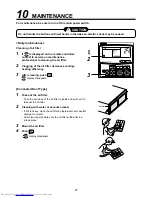
Page 27: ... Clogging of the air filter decreases cooling heating efficiency 3 After cleaning push display disappears Concealed Duct Type 1 Take out the air filter Push the extrusion of the air filter to inside and pull out it to take out the air filter 2 Cleaning with water or vacuum cleaner If dirt is heavy clean the air filter by tepid water with neutral detergent or water After cleaning with water dry the...

Page 28: ... the number of high concentration buildings however the installation of multi air conditioner systems is on the increase because of the need for effective use of floor space individual control energy conservation by curtailing heat and carrying power etc Most importantly the multi air conditioner system is able to replenish a large amount of refrigerant compared with conventional individual air co...

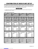
Page 29: ... 0003 Have you changed lighting time of filter sign If not fill check mark in NO CHANGE and fill check mark in ITEM if changed respectively For check method refer to Applicable controls in this sheet Filter sign lighting time Filter sign lighting time Filter sign lighting time Filter sign lighting time Item code 01 Item code 01 Item code 01 Item code 01 o NO CHANGE o NO CHANGE o NO CHANGE o NO CHA...

Reviews: