background image

Installation Manual

English

Indoor Unit

Model name:

Concealed Duct High Static Pressure Type

MMD-AP0184H-E
MMD-AP0244H-E
MMD-AP0274H-E
MMD-AP0364H-E
MMD-AP0484H-E

AIR CONDITIONER (MULTI TYPE)

Installation Manual

+00EH99879501_01EN.book  Page 1  Monday, March 14, 2011  10:06 PM

Summary of Contents for MMD-AP0184H-E

Page 1: ...r Unit Model name Concealed Duct High Static Pressure Type MMD AP0184H E MMD AP0244H E MMD AP0274H E MMD AP0364H E MMD AP0484H E AIR CONDITIONER MULTI TYPE Installation Manual 00EH99879501_01EN book Page 1 Monday March 14 2011 10 06 PM ...

Page 2: ... the refrigerant handling and piping work involved in installation relocation and removal has the qualifications pertaining to this refrigerant handling and piping work as stipulated by the local laws and regulations and he or she is a person who has been trained in matters relating to refrigerant handling and piping work on the air conditioners made by Toshiba Carrier Corporation or alternatively...

Page 3: ...onal protective toe cap Repair of outdoor unit Gloves to provide protection for electricians and from heat Warning indications on the air conditioner unit Warning indication Description WARNING ELECTRICAL SHOCK HAZARD Disconnect all remote electric power supplies before servicing WARNING Moving parts Do not operate unit with grille removed Stop the unit before the servicing CAUTION High temperatur...

Page 4: ... installed appropriately a unit may topple over or fall down causing an accident If refrigerant gas has leaked during the installation work ventilate the room immediately If the leaked refrigerant gas comes in contact with fire noxious gas may generate Use forklift to carry in the air conditioner units and use winch or hoist at installation of them Helmet must be worn to protect your head from fal...

Page 5: ...dizing membrane or oil and its pressure is approx 1 6 times higher than that of refrigerant R22 Accompanied with the new refrigerant refrigerating oil has also been changed Therefore do not let water dust former refrigerant or refrigerating oil enter the refrigerating cycle during installation work To prevent charging an incorrect refrigerant and refrigerating oil the sizes of connecting sections ...

Page 6: ... would be compromised by wetness If the drain has become blocked or when the humidity is over 80 condensation from the indoor unit will drip possibly causing damage to anything underneath In the case of the wireless type of system rooms with the inverter type of fluorescent lighting or locations exposed to direct sunlight The signals from the wireless remote controller may not be sensed Locations ...

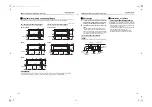
Page 7: ...ing bolts washer and nuts for installing the indoor unit these are not supplied Installation of hanging bolt Use M10 hanging bolts 4 pcs to be local procure Matching to the existing structure set pitch according to size in the unit external view as shown below Installation of indoor unit Treatment of ceiling The ceiling differs according to structure of building For details consult your constructo...

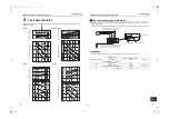
Page 8: ...short circuits design the duct work so that the intake and discharge openings are not adjacent to each other 2 The indoor unit does not have a built in air filter Always install the air filter Local procure in a location that permits easy maintenance such as behind the intake grille If no air filter is installed dust will collect in the heat exchanger which may cause the air conditioner to fail or...

Page 9: ...Air volume lower limit Outside static pressure Pa Air volume upper limit Air volume m3 h Fan motor current A 2 0 2 5 3 0 1 5 0 5 250 200 150 50 100 1500 2000 2100 2500 0 50 Hz 60 Hz Standard air volume 2100 m3 h High static pressure tap Medium static pressure tap Low static pressure tap High static pressure tap M edium static pressure tap L o w s t a t i c p r e s s u r e t a p Air volume lower li...

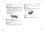
Page 10: ...door unit Incomplete heat insulating may cause dewing Pipe material size and insulator The following materials for piping work and insulating process are procured locally Connecting drain pipe Insert the drain hose into the connector until the hose can go no farther REQUIREMENT Connect the hard vinyl chloride pipes certainly so that water does not leak by using adhesive agent for vinyl chloride It...

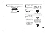
Page 11: ...ause gas leakage 2 Insert a flare nut into the pipe and flare the pipe Use the flare nut provided with the unit or the one used for the R410A refrigerant The flaring dimensions for R410A are different from the ones used for the conventional R22 refrigerant A new flare tool manufactured for use with the R410A refrigerant is recommended but the conventional tool can still be used if the projection m...

Page 12: ...elephone earth wires Appliance shall be installed in accordance with national wiring regulations Capacity shortage of power circuit or incomplete installation may cause an electric shock or a fire CAUTION If incorrect incomplete wiring is carried out it will cause an electrical fire or smoke Install an earth leakage breaker that is not tripped by shock waves If an earth leakage breaker is not inst...

Page 13: ...l line wiring 2 core shield wire Wire size Up to 1000 m 1 25 mm Up to 2000 m 2 0 mm Remote controller wiring remote controller inter unit wiring Wire size 0 5 mm to 2 0 mm Total wire length of remote controller wiring and remote controller inter unit wiring L L1 L2 Ln In case of wired type only Up to 500 m In case of wireless type included Up to 400 m Total wire length of remote controller inter u...

Page 14: ... up by performing operations on the outdoor interface circuit board While the automatic addresses are being set up no remote controller operations can be performed Setup takes up to 10 minutes usually about 5 minutes When the power is turned on after automatic address setup It takes up to 10 minutes usually about 3 minutes for the outdoor unit to start operating after the power has been turned on ...

Page 15: ...near the ceiling Follow to the basic operation procedure 1 2 3 4 5 6 For the CODE No in Procedure 3 specify 06 For the set data in Procedure 4 select the SET DATA of shift value of detection temperature to be set up from the following table SET DATA Filter sign term 0000 None 0001 150 H 0002 2500 H Factory default 0003 5000 H 0004 10000 H SET DATA Detection temperature shift value 0000 No shift 00...

Page 16: ...ed using this method do NOT forget to release the shorting of CN72 after the test run is completed Operate the unit with the wired remote controller as usual For the procedure of the operation refer to the attached Owner s Manual to the outdoor unit A forced test run can be executed in the following procedure even if the operation stops by thermostat OFF In order to prevent a serial operation the ...

Page 17: ...lter 1 Push the button to stop the operation then turn off the circuit breaker After the cooling or dry operation the ventilation fan keeps running for self cleaning Push the button twice to stop the operation 3 1 2 Inspection before maintenance Following inspection must be carried out by a qualified installer or qualified service person Maintenance List Parts Inspection method Heat exchanger Acce...

Page 18: ...in memory up to 4 errors The log can be confirmed from both operating status and stop status 1 When and buttons are pushed simultaneously for 4 seconds or more the following display appears If is displayed the mode enters in the error log mode 01 Order of error log is displayed in CODE No Error code is displayed in CHECK Indoor unit address in which an error occurred is displayed in Unit No 2 Ever...

Page 19: ...on error Remote controller E03 97 Communication error between indoor unit and remote controller Detected at indoor unit side Indoor unit E04 04 Communication circuit error between indoor outdoor unit Detected at indoor unit side Indoor unit E06 E06 No of indoor units in which sensor has been normally received 04 Decrease of No of indoor units I F E07 Communication circuit error between indoor outd...

Page 20: ...eak down IPDU H02 H02 01 Comp 1 side 02 Comp 2 side 03 Comp 3 side 1d Compressor trouble lock IPDU H03 H03 01 Comp 1 side 02 Comp 2 side 03 Comp 3 side 17 Current detect circuit system error IPDU H04 H04 44 Comp 1 case thermo operation I F H05 H05 TD1 sensor miswiring I F H06 H06 20 Low pressure protective operation I F H07 H07 d7 Oil level down detective protection I F H08 H08 01 TK1 sensor error...

Page 21: ... Comp 1 side 02 Comp 2 side 03 Comp 3 side AF ALT Phase missing detection Power failure detection Inverter DC voltage error comp Inverter DC voltage error comp Inverter DC voltage error comp I F P07 P07 01 Comp 1 side 02 Comp 2 side 03 Comp 3 side IC ALT Heat sink overheat error IPDU I F P09 P09 Detected heat storage address 47 ALT No heat storage unit water error Heat storage unit P10 P10 Detecte...

Page 22: ...omp 3 Fan 0F Comp 1 Comp 2 Comp 3 Fan Check code Wireless remote controller Check code name Judging device Central control device indication Outdoor unit 7 segment display AI NET central control display Sensor block display of receiving unit Auxiliary code Operation Timer Ready Flash C05 Sending error in TCC LINK central control device TCC LINK C06 Receiving error in TCC LINK central control devic...

Page 23: ...te PLYMOUTH Devon PL6 7DB United Kingdom Hereby declares that the machinery described below Generic Denomination Air Conditioner Model type MMD AP0184H E MMD AP0244H E MMD AP0274H E MMD AP0364H E MMD AP0484H E Commercial name Super Modular Multi System Air Conditioner Super Heat Recovery Multi System Air Conditioner Mini Super Modular Multi System Air Conditioner MiNi SMMS series Complies with the...

Page 24: ...10A which is used in multi air conditioners is 0 3 kg m3 NOTE 1 If there are 2 or more refrigerating systems in a single refrigerating device the amounts of refrigerant should be as charged in each independent device For the amount of charge in this example The possible amount of leaked refrigerant gas in rooms A B and C is 10 kg The possible amount of leaked refrigerant gas in rooms D E and F is ...

Page 25: ...ighting time CODE NO 01 F NO CHANGE F NONE 0000 F 150H 0001 F 2500H 0002 F 5000H 0003 F 10000H 0004 Filter sign lighting time CODE NO 01 F NO CHANGE F NONE 0000 F 150H 0001 F 2500H 0002 F 5000H 0003 F 10000H 0004 Filter sign lighting time CODE NO 01 F NO CHANGE F NONE 0000 F 150H 0001 F 2500H 0002 F 5000H 0003 F 10000H 0004 Filter sign lighting time CODE NO 01 F NO CHANGE F NONE 0000 F 150H 0001 F...

Page 26: ...EH99879599 00EH99879501_01EN book Page 33 Monday March 14 2011 10 06 PM ...

Reviews: