–
94
–
No. Part name
Procedure
Remarks
⑤
⑥
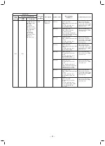
Drain pump
Float switch
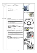
1. Detachment
1) Perform works until opening of the electric parts box
cover in works of 1 of
②
.
2) Remove the connectors which connect to float switch
of the drain pump from the control P.C. board.
CN34 : Float switch (3P, Red)
CN504 : Drain pump (2P, White)
3) Loosen the fixing screws (2 positions) of the check cover
and then take out the check cover.
(To the check cover, the drain pump and float switch are
attached.)
4) Pick up the hose band, shift from the pump connecting
part, remove the drain hose and then remove the check
cover.
5) Remove screws which fix the drain pump assembly and
then remove the drain pump assembly. (Ø4 x 10, 3 pcs.)
6) Remove the resin nut switch and then remove the float
switch from the fixing plate.
2. Attachment
1) Using the removed screws, fix the drain pump assembly
as original.
2) Using the removed resin nut, fix the float switch as
original.
3) Connect the drain hose as original and then attach the
hose band.
Connector
position
CN34
CN504
Entering part
Fixing screws
Screw
Check cover
Resin nut
Drain pump
Float switch
Drain hose
Hose band
NOTE
Insert the drain hose to the end of the drain pump.
4) Connect the drain pump and the float switch wiring as
original and close the electric parts box cover for fixing.
Be sure to perform wiring in the electric parts box as
original.
5) Enter the corners (2 positions) of the check cover in the
entering part and then fix it using fixing screws
(2 positions).
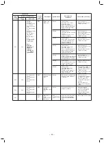
PMV
motor
1. Detachment
1) Perform works until opening of the electric parts box
cover in works of 1 of
②
.
2) Perform works until opening of the check cover in
works of 1 of
⑤
.
3) Remove relay connector of the PMV motor.
4) As shown in the right figure, using a double spanner,
open the check port at the side face and then remove
the PMV motor.
Relay connector of PMV motor
2. Attachment
1) Connect the relay connector of the PMV motor as
original and close the electric parts box cover for fixing.
Be sure to perform wiring in the electric parts box as
original.
2) Enter the corners (2 positions) of the check cover in the
entering part and then fix it using fixing screws
(2 positions).
Drain hose
Summary of Contents for MMD-AP0186HP-E
Page 20: ... 20 4 WIRING DIAGRAMS ...


