background image

– 17 –

Check codes and parts to be checked

Check method

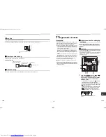
On the remote control (Wired remote control, Central control remote control) and the interface P.C. board of the 
outdoor unit (I/F), a check display LCD (Remote control) or 7-segment display (on the outdoor interface P.C. board) 
to display the operation is provided. Therefore the operation status can be known. With this self-diagnosis function, 
a trouble or position with trouble of the air conditioner can be found as shown in the table below.

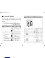
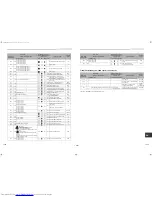
Check code list

The following list shows each check code. Find the check contents from the list according to part to be checked.
• To check from indoor remote control: See “Wired remote control display” in the list.
• To check from outdoor unit: See “Outdoor 7-segment display” in the list.
• To check from indoor unit with a wireless remote control: See “Sensor block display of receiving unit” in the list.

IPDU : Intelligent Power Drive Unit

: Lighting, 

: Flashing, 

: Goes off

ALT : Flashing is alternately when there are two flashing LED.
SIM : Simultaneous flashing when there are two flashing LED.

Check code

Wireless remote control

Check code name

Judging 

device

Wired remote 

control display

Outdoor 7-segment display

Sensor block display of 

receiving unit

Auxiliary code

Operation Timer Ready Flash

E01

Communication trouble between indoor 

and remote control 

(Detected at remote control side)

Remote 

control

E02

Remote control transmission trouble

Remote 

control

E03

Communication trouble between indoor 

and remote control (Detected at indoor 

side)

Indoor

E04

Communication circuit trouble between 

indoor / outdoor (Detected at indoor 

side)

Indoor

E06

E06 No. of indoor units in which sensor has been normally 

received

Decrease of No. of indoor units

I/F

E07

Communication circuit trouble between 

indoor / outdoor (Detected at outdoor 

side)

I/F

E08

E08 Duplicated indoor addresses

Duplicated indoor addresses

Indoor / I/F

E09

Duplicated header remote controls

Remote 

control

E10

Communication trouble between indoor 

MCU

Indoor

E12

E12 01: Indoor / Outdoor communication

02: Communication between outdoor units

Automatic address start trouble

I/F

E15

E15

Indoor is nothing during automatic 

addressing

I/F

E16

E16 00: Capacity over

01 ~:No. of connected units

Capacity over / No. of connected indoor units

Combined capacity of indoor units 

exceeds 120% of combined capacity of 

outdoor units. (SMMS-i only)

I/F

E18

Communication trouble between indoor units

Indoor

E19

E19 00: Header is nothing

02: Two or more header units

Outdoor header units quantity trouble

I/F

E20

E20 01: Outdoor of other line connected

02: Indoor of other line connected

Other line connected during automatic 

address

I/F

E23

E23

Sending trouble in communication 

between outdoor units

I/F

E25

E25

Duplicated follower outdoor addresses

I/F

E26

E26 No. of outdoor units which received signal normally

Decrease of No. of connected outdoor units

I/F

E28

E28 Detected outdoor unit number

Follower outdoor unit trouble

I/F

E31

E31

IPDU communication trouble

I/F

F01

ALT Indoor TCJ sensor trouble

Indoor

F02

ALT Indoor TC2 sensor trouble

Indoor

F03

ALT Indoor TC1 sensor trouble

Indoor

F04

F04

ALT TD1 sensor trouble

I/F

F05

F05

ALT TD2 sensor trouble

I/F

F06

F06 TE1 sensor

TE2 sensor

ALT TE1 sensor trouble

TE2 sensor trouble

I/F

F07

F07

ALT TL sensor trouble

I/F

F08

F08

ALT TO sensor trouble

I/F

F09

F09 01: TG1

02: TG2

TG1 sensor trouble

TG2 sensor trouble

I/F

F10

ALT Indoor TA sensor trouble

Indoor

F11

— TF sensor

ALT TF sensor trouble

Indoor

F12

F12 01: TS1 sensor

03: TS3 sensor

ALT TS1 sensor trouble, TS3 sensor trouble

I/F

F13

F13

01: Comp. 1 side

02: Comp. 2 side

03: Comp. 3 side 

ALT TH sensor trouble

IPDU

F15

F15

ALT Outdoor temp. sensor miswiring (TE1, TL)

I/F

F16

F16

ALT Outdoor pressure sensor miswiring (Pd, Ps)

I/F

F22

F22

ALT TD3 trouble

I/F

F23

F23

ALT Ps sensor trouble

I/F

F24

F24

ALT Pd sensor trouble

I/F

F29

SIM Indoor other trouble

Indoor

F31

F31

SIM Indoor EEPROM trouble

I/F

H01

H01

01: Comp. 1 side

02: Comp. 2 side

03: Comp. 3 side

Compressor break down

IPDU

H02

H02

01: Comp. 1 side

02: Comp. 2 side

03: Comp. 3 side

Compressor trouble (lock)

IPDU

H03

H03

01: Comp. 1 side

02: Comp. 2 side

03: Comp. 3 side

Current detect circuit system trouble

IPDU

H05

H05

TD1 miswiring

I/F

H06

H06

Low pressure protective operation

I/F

H07

H07

Oil level down detective protection

I/F

Check code

Wireless remote control

Check code name

Judging 

device

Wired remote 

control display

Outdoor 7-segment display

Sensor block display of 

receiving unit

Auxiliary code

Operation Timer Ready Flash

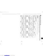
Sub-

code

A3-IPDU

Fan- 

IPDU Sub-

code

A3-IPDU Fan- 

IPDU

1 2 3 1 2

1 2 3 1 2

01

0D

 

02

0E

  

03

 

0F

   

04

11

05

12

06

 

13

 

07

  

18

 

08

19

 

09

1A

 

0A

1B

 

 

0B

 

Circle (

): IPDU trouble

0C

 

33-EN

34-EN

+00EHEH99887601.book  Page 17  Thursday, April 21, 2016  9:44 AM

Summary of Contents for MMD-AP0481HF2UL

Page 1: ...e Outside Air Unit MMD AP0481HF2UL MMD AP0721HF2UL MMD AP0961HF2UL Installation Manual Français Installation Manual 1 English Manuel du propriétaire 21 For commercial use Pour usage commercial 00EHEH99887601 book Page 1 Thursday April 21 2016 9 44 AM ...

Page 2: ...cable controls 14 12 Test run 15 13 Troubleshooting 16 Please read this Installation Manual carefully before installing the Air Conditioner This Manual describes the installation method of the indoor unit For installation of the outdoor unit follow the Installation Manual attached to the outdoor unit ADOPTION OF NEW REFRIGERANT This Air Conditioner uses R410A an environmentally friendly refrigeran...

Page 3: ...at a height 8 2 4 m or more from the floor If you insert your hands or others directly into the unit while the air conditioner operates it is dangerous because you may contact with revolving fan or active electricity If refrigerant gas has leaked during the installation work ventilate the room immediately If the leaked refrigerant gas comes in contact with fire noxious gas may generate After the i...

Page 4: ...ing section 8 For heat insulation of hanging bracket AP048 type 4 pieces 3 2 80 mm AP072 096 type 4 pieces 5 5 140 mm 3 System control of Outside Air Unit System able to be combined The Outside Air Unit is connectable to SMMS Super Modular Multi system However this is not connectable to SHRM Super Heat Recovery Multi system Keep the height difference between the Outside Air Units to 1 97 0 5 m or ...

Page 5: ... works The quality of the items stored may be degraded Locations where high frequencies are generated by inverter equipment in house power generators medical equipment or communication equipment Malfunctioning or control trouble in the air conditioner or noise may adversely affect the equipment s operation Locations where there is anything under the unit installed that would be compromised by wetn...

Page 6: ...9 6 1260 Ø1 2 12 7 flare Ø7 8 22 2 brazing B Hanging bolt pitch 4 M0 4 10 hanging bolt Locally procured 50 7 1288 Hanging bolt pitch Electrical control box A 3 4 87 52 3 1328 Refrigerant pipe connecting port Liquid side C Drain pipe connecting port Refrigerant pipe connecting port Gas side D 19 5 496 2 6 66 8 6 218 5 9 150 1 9 49 49 8 1266 0 7 18 2 4 60 27 5 699 33 3 845 Treatment of ceiling The c...

Page 7: ...all the filter chamber on the intake side of the indoor unit Attach the long life prefilter and high efficiency filter to the filter chamber to remove dust Send outside air to the inside of the indoor unit and the area being air conditioned If no air filter is installed dust will collect in the heat exchanger which may cause the air conditioner to fail or to leak Be sure to set the duct at air int...

Page 8: ... construction 1 Air intake duct Connect the air intake duct Locally procured to the inlet flange Wrap aluminum tape around connecting part between the air intake port flange and duct or provide sealer so that air does not leak For the outside air intake port attach a hood so that outside air is sucked from lower side And attach wire netting etc to the air intake of the hood Set the air intake duct...

Page 9: ... A Middle static pressure tap High static pressure tap Low static pressure tap Air flow rate cfm MMD AP072 type Standard air volume 989 cfm Lower limit air volume 693 cfm Upper limit air volume 1088 cfm REQUIREMENT Set a volume damper to the air supply duct and then adjust the air volume so that it is kept in the range of 70 to 110 against the standard air volume 1 2 230V Fan characteristics 2 2 2...

Page 10: ...n if change of the external static pressure is required due to the duct resistance REQUIREMENT When the external static pressure was changed enter the changed static pressure value in the identification plate of the unit MMD AP048 AP072 type MMD AP096 type Terminal block No Fan motor wiring Remarks F1 Low static pressure tap Blue F2 Middle static pressure tap Orange At shipment from factory F3 Hig...

Page 11: ...e material size and insulator The following materials for piping work and insulating process are locally procured Connecting drain pipe REQUIREMENT Using adhesive agent for vinyl chloride connect the hard vinyl chloride pipes certainly so that water does not leak It takes some time to dry and indurate the adhesive agent Refer to the manual of adhesive agent Do not apply any extra force on the conn...

Page 12: ... 7 0 65 16 6 5 8 15 9 0 78 19 7 Outer dia of connecting pipe mm Tightening torque Unit ft lbs N m 3 8 9 5 24 31 33 42 1 2 12 7 37 46 50 62 5 8 15 9 46 57 63 77 Work using double spanner Tightening torque of flare pipe connections Pressure of R410A is higher than that of R22 Approx 1 6 times Therefore using a torque wrench tighten the flare pipe connecting sections which connect the indoor and outd...

Page 13: ...ause overheat or seizure may be caused Indoor unit power supply For the power supply of the indoor unit prepare the exclusive power supply separated from that of the outdoor unit Power supply Control wiring Central control wiring 2 core with non polarity wires are used for the control wiring between indoor unit and outdoor unit and Central control wiring To prevent noise trouble use 2 core shielde...

Page 14: ...trical control box at servicing or other purpose The low voltage circuit is provided for the remote control Do not connect the high voltage circuit Remove the cover of the electrical control box by taking off the mounting screws 2 positions Tighten the screws of the terminal block and fix the wires with cord clamp attached to the electrical control box Do not apply tension to the connecting sectio...

Page 15: ...n turned on Before the air conditioner was shipped from the factory all units are set to STANDARD factory default If necessary change the indoor unit settings The settings are changed by operating the wired remote control The settings cannot be changed using only a wireless remote control simple remote control or group control remote control by itself so install a wired remote control separately a...

Page 16: ...rom the remote control terminal blocks A B of the indoor unit connected with a remote control to the remote control terminal blocks A B of the other indoor unit Non polarity For address setup refer to the Installation Manual attached to the outdoor unit SET DATA Filter sign term 0000 None 0001 150 H 0002 2500 H Factory default 0003 5000 H 0004 10000 H SET DATA 0000 0001 Filter sign term Normal Hal...

Page 17: ...isplay part of the remote control The check code is only displayed during the operation If the display disappears operate the air conditioner according to the following Confirmation of check code log for confirmation Confirmation of check code log When a problem occurred on the air conditioner the check code log can be confirmed with the following procedure The check code log is stored in memory u...

Page 18: ...ed capacity of indoor units exceeds 120 of combined capacity of outdoor units SMMS i only I F E18 Communication trouble between indoor units Indoor E19 E19 00 Header is nothing 02 Two or more header units Outdoor header units quantity trouble I F E20 E20 01 Outdoor of other line connected 02 Indoor of other line connected Other line connected during automatic address I F E23 E23 Sending trouble in...

Page 19: ...5 01 TS condition 02 TD condition ALT Gas leak detection I F P17 P17 ALT Discharge temp TD2 trouble I F P18 P18 ALT Discharge temp TD3 trouble I F P19 P19 Detected outdoor unit number ALT 4 way valve inverse trouble I F P20 P20 ALT High pressure protective operation I F P22 P22 0 IGBT circuit 1 Location detection circuit trouble 3 Motor lock up trouble 4 Motor current was detected C Abnormal tempe...

Page 20: ...ng systems in a single refrigerating device the amounts of refrigerant should be as charged in each independent device For the amount of charge in this example The possible amount of leaked refrigerant gas in rooms A B and C is 22 lbs 10 kg The possible amount of leaked refrigerant gas in rooms D E and F is 33 lbs 15 kg NOTE 2 The standards for minimum room volume are as follows 1 No partition sha...

Page 21: ...ectively For check method refer to APPLICABLE CONTROLS in this manual Filter sign lighting time CODE NO 01 NO CHANGE NONE 0000 150H 0001 2500H 0002 5000H 0003 10000H 0004 Filter sign lighting time CODE NO 01 NO CHANGE NONE 0000 150H 0001 2500H 0002 5000H 0003 10000H 0004 Filter sign lighting time CODE NO 01 NO CHANGE NONE 0000 150H 0001 2500H 0002 5000H 0003 10000H 0004 Filter sign lighting time C...

Page 22: ...ctrique 32 11 Commandes utilisables 34 12 Essai de fonctionnement 35 13 Résolution des problèmes 36 Veuillez lire attentivement ce manuel avant d installer le climatiseur Ce manuel traite de la méthode d installation de l unité intérieure Pour l installation de l unité extérieure reportez vous au manuel d installation livré avec cet équipement ADOPTION DU NOUVEAU FLUIDE FRIGORIGÈNE Ce climatiseur ...

Page 23: ...mettre les mains ou d y faire pénétrer des outils car vous pouvez toucher aux pales du ventilateur en action ou entrer en contact direct avec l électricité Si le gaz frigorigène a fui durant l installation aérez immédiatement la pièce Si le gaz réfrigérant qui a fui entre en contact avec le feu un gaz nocif peut se dégager Après l installation assurez vous que le gaz réfrigérant ne fuit pas Si le ...

Page 24: ...8 Pour l isolation thermique du support d accrochage Type AP048 4 pièces 3 2 po 80 mm Types AP072 096 4 pièces 5 5 po 140 mm 3 Commande du système pour l unité d aspiration d air extérieur Système peut être combiné Il est possible de connecter l unité d aspiration d air extérieur au SMMS système multiple modulaire Toutefois elle ne peut pas être raccordée au SHRM système multiple de récupération d...

Page 25: ...ents de précision ou d œuvres d art Les éléments stockés pourraient se dégrader Les endroits dans lesquels de hautes fréquences sont générées par des inverseurs des groupes électrogènes internes du matériel médical ou de communication Un dysfonctionnement un mauvais contrôle du climatiseur ou un bruit au niveau de ce dernier pourrait nuire au bon fonctionnement de l équipement Les endroits dans le...

Page 26: ... entre les boulons de suspension Boulon de suspension 4 M0 4 10 acheté séparément 50 7 1288 Distance entre les tiges filetées poursuspension Boîtier de commande électrique A 3 4 87 52 3 1328 Orifice de raccordement du tuyau du réfrigérant Côté liquide C Orifice de raccordement du tuyau d évacuation Port de raccordement du tuyau de réfrigérant Côté gaz D 19 5 496 2 6 66 5 9 150 1 9 49 49 8 1266 0 7...

Page 27: ...filtration du côté admission de l unité intérieure Fixez le filtre à durée de vie longue et le filtre à haut rendement à la chambre de filtration pour retirer la poussière Envoyez de l air extérieur dans l unité intérieure et la surface climatisée Si aucun filtre à air n est installé la poussière se dépose dans l échangeur thermique ce qui peut conduire à une défaillance ou à une fuite du climatis...

Page 28: ...nduit d aspiration d air vendu séparément à la bride d entrée Enveloppez avec un ruban d aluminium le raccord entre le conduit et la bride de l orifice d aspiration d air ou un isolant pour éviter les fuites d air Pour l orifice d aspiration d air extérieur fixez un capot pour que l air extérieur soit aspiré par le côté inférieur Fixez ensuite le treillis etc à l admission d air du capot Placez le...

Page 29: ...ute Robinet de pression statique moyenne Robinetdepression statique basse Robinet de pression statique haute Type MMD AP072 Volume d air standard 989 cfm volume d air de limite inférieure 693 cfm volume d air de limite supérieure 1088 cfm EXIGENCE Réglez un régulateur de volume d air au conduit d admission d air et réglez le volume d air dans une plage comprise entre 70 et 110 du volume d air stan...

Page 30: ...expédition de l usine Modifiez le raccordement de câble en fonction de la pression statique extérieure de la résistance de la gaine EXIGENCE Lorsque la pression station externe est modifiée inscrivez la valeur modifiée de la pression statique sur la fiche signalétique de l unité Type MMD AP048 type AP072 Type MMD AP096 N de bornier Câblage du moteur du ventilateur Remarques F1 Robinet de pression ...

Page 31: ...ée à l aide de l isolant thermique fourni Tuyauterie dimension et isolant Les matériaux suivants servant aux travaux de plomberie et d isolation sont achetés sur place Raccordement du tuyau d évacuation EXIGENCE A l aide d un adhésif pour tuyau en chlorure de vinyle raccordez bien les tuyaux en chlorure de vinyle dur de sorte qu ils ne fuient pas L adhésif sèche et durcit après un bon moment Repor...

Page 32: ... 8 9 5 24 31 33 42 1 2 12 7 37 46 50 62 5 8 15 9 46 57 63 77 Serrage à l aide de deux clés plates Couple de serrage des raccords des tuyaux évasés La pression du R410A est supérieure à celle du R22 Environ 1 6 fois En conséquence utilisez une clé dynamométrique et serrez les raccords coniques des sections de raccordement des unités intérieure et extérieure aux couples prescrits Les raccordements i...

Page 33: ...de l unité intérieure Pour l alimentation électrique de l unité intérieure préparez l alimentation électrique exclusive séparée de celle de l unité extérieure Alimentation électrique Câblage de commande câblage de commande centralisée Des câbles 2 conducteurs sans polarité sont utilisés pour le câblage de commande entre l unité intérieure et l unité extérieure ainsi que pour le câblage de commande...

Page 34: ...ctriques lors de l entretien etc Le circuit basse tension est destiné à la télécommande Ne raccordez pas le circuit haute tension Retirez le couvercle du boîtier de commandes électriques en dévissant pour cela les vis de montage 2 positions Serrez les vis de la plaquette de connexion puis fixez les câbles avec la bride de serrage fournie avec le boîtier des commandes électriques N exercez aucune p...

Page 35: ... Modifiez les paramètres de l unité intérieure si nécessaire Vous pouvez modifier les réglages à l aide de la télécommande avec fil Les réglages ne peuvent pas être modifiés au moyen d une télécommande sans fil d une télécommande simple ou d une télécommande de commande centralisée uniquement Installez également une télécommande avec fil séparément Procédure de base pour la modification des paramè...

Page 36: ...intérieure connectée plaquettes de connexion A B à la télécommande de l autre unité intérieure plaquettes de connexion A B Pas de polarité Pour la configuration des adresses reportez vous au manuel d installation de l unité extérieure SET DATA Minuterie d alarme du filtre 0000 Aucun 0001 150 H 0002 2500 H Réglage par défaut en usine 0003 5000 H 0004 10000 H SET DATA 0000 0001 Minuterie d alarme du...

Page 37: ...la télécommande Le code d erreur n est présent que pendant le fonctionnement Si l affichage disparaît faites fonctionner le climatiseur conformément au point suivant Confirmation du journal de code d erreur pour la vérification Confirmation du journal de code d erreur Lorsqu un problème survient au niveau du climatiseur le journal de code d erreur peut être vérifié en procédant comme suit Le journ...

Page 38: ...acité nombre d unités intérieures connectées La capacité combinée des unités intérieures dépasse 120 de la capacité combinée des unités extérieures SMMS i uniquement I F E18 Trouble de communication entre unités intérieures Intérieure E19 E19 00 La tête ne va pas 02 Deux ou plusieurs unités intérieures Trouble de quantité d unités extérieures principales I F E20 E20 01 Autre ligne extérieure conne...

Page 39: ...Trouble de détection de retour de liquide extérieur I F P15 P15 01 Condition TS 02 Condition TD ALT Fuite de gaz détectée I F P17 P17 ALT Temp de sortie Trouble TD2 I F P18 P18 ALT Temp de sortie Trouble TD3 I F P19 P19 Numéro d unité extérieure détecté ALT Trouble vanne inverse 4 voies I F P20 P20 ALT Fonctionnement en mode de protection contre les hautes pressions I F P22 P22 0 Circuit IGBT 1 Tr...

Page 40: ...argées dans chaque dispositif indépendant Pour la quantité de charge dans cet exemple La quantité possible de fuite de réfrigérant dans les pièces A B et C est 22 lbs 10 kg La quantité possible de fuite de réfrigérant dans les pièces D E et F est 33 lbs 15 kg REMARQUE 2 Les normes pour les volumes minimum des pièces sont les suivantes 1 Sans cloison portion ombrée 2 S il existe une ouverture effec...

Page 41: ...cochez la case pour AUCUN CHANGEMENT et cochez la case pour ITEM si vous l avez changée Pour accéder à une méthode de contrôle consultez les COMMANDES APPLICABLES de ce manuel Éclairage du témoin du filtre CODE N 01 AUCUN CHANGEMENT AUCUN 0000 150H 0001 2500H 0002 5000H 0003 10000H 0004 Éclairage du témoin du filtre CODE N 01 AUCUN CHANGEMENT AUCUN 0000 150H 0001 2500H 0002 5000H 0003 10000H 0004 ...

Page 42: ... 41 MEMO 00EHEH99887601 book Page 41 Thursday April 21 2016 9 44 AM ...

Page 43: ... 42 MEMO 00EHEH99887601 book Page 42 Thursday April 21 2016 9 44 AM ...

Page 44: ...EB99807601 00EHEH99887601 book Page 43 Thursday April 21 2016 9 44 AM ...

Page 45: ...tops automatically in order to protect the equipment In this case continue the operation by selecting HEAT mode In HEAT mode if temperature of the outside air is under 23 F the operation stops automatically in order to protect the equipment When operating the air conditioner with the outside air temp under 23 F minimum 5 F set temp of the outside air to be taken in to 23 F or upper using a duct he...

Page 46: ...onctionnement s arrête automatiquement pour protéger l équipement Dans ce cas continuez le fonctionnement en sélectionnant le mode HEAT En mode HEAT si la température de l air extérieur est inférieure à 23 F le fonctionnement s arrête automatiquement pour protéger l équipement Lors du fonctionnement du climatiseur avec une température d air extérieur en dessous de 23 F minimum 5 F réglez la tempér...

Reviews: