background image

– 10 –

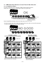
1-1. S-MMS System Specifications to Connect Fresh Air Intake Indoor Unit

1-1-1. Combination Conditions

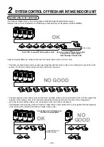
The fresh air intake indoor unit is connectable to S-MMS (Super Modular Multi system).
However this is not connectable to S-HRM (Super Heat Recovery Multi system).

[Installation example

of all fresh air intake indoor unit system]

[Installation example

of intermingled system]

OK

80 to 100% to capacity of the outdoor units

Up to two fresh air intake indoor units 

occupy 30% or less against 

total capacity of indoor units

0.5m or less

NO GOOD

OK

NG

Outdoor unit

Inside of ceiling

All fresh air intake indoor unit system

Indoor air conditioner

Outdoor unit

Intermingled system with 
indoor air conditioner 

Fresh air intake 
indoor unit

Indoor air conditioner

fresh air intake 
indoor unit

Fresh air intake 
indoor unit

Keep the height difference between the fresh air intake indoor units to 0.5m or less.

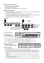
• The fresh air intake indoor unit is usually used together with the indoor units on one line of the multi system.

The fresh air intake indoor unit only cannot be connected.

Summary of Contents for MMD-AP0481HFE

Page 1: ...AL FRESH AIR INTAKE INDOOR UNIT for S MMS INDOOR UNIT MMD AP0481HFE MMD AP0721HFE MMD AP0961HFE OUTDOOR UNIT For Service Manual of S MMS and outdoor unit refer to the Service Manual File No A03 009 A03 010 PRINTED IN JAPAN Jun 2007 ToMo ...

Page 2: ...NDOOR UNIT 9 1 1 S MMS System Specifications to Connect Fresh Air Intake Indoor Unit 10 2 SPECIFICATIONS 12 2 1 Fresh Air Intake Indoor Unit for S MMS 12 3 SPECIFICATIONS OF ELECTRICAL PARTS 13 3 1 Fresh Air Intake Indoor Unit for S MMS 13 4 OWNER S MANUAL 14 PARTS NAME 14 PARTS NAME OF REMOTE CONTROLLER 15 CORRECT USAGE 17 TIMER OPERATION 19 5 INSTALLATION MANUAL 20 Accessory parts and Parts to b...

Page 3: ...unction during Test Operation 60 10 4 Function Selection Setting for Indoor Air Conditioner For setup be sure to use a wired remote controller 62 10 5 Applicable Control of Indoor Air Conditioner 64 11 TROUBLE DIAGNOSES 69 11 1 Summary of trouble diagnoses 69 11 2 Checking Method 70 11 3 Trouble Diagnoses by Check Display of the Remote Controller 73 11 4 Check Code and Check Position Displayed on ...

Page 4: ...bles of the product after work when an incorrect work has been executed Mark Explanation Indicates prohibited items Forbidden items to do The sentences near an illustrated mark describe the concrete prohibited contents Indicates mandatory items Compulsory items to do The sentences near an illustrated mark describe the concrete mandatory contents Indicates cautions Including danger warning The sent...

Page 5: ... refrigerant R22 etc never use R410A If different types of refrigerant are mixed abnormal high pressure generates in the refrigerat ing cycle and an injury due to breakage may be caused Do not charge refrigerant additionally If charging refrigerant additionally when refrigerant gas leaks the refrigerant composition in the refrigerating cycle changes resulted in change of air conditioner characteri...

Page 6: ...stallation work follow to the Installation Manual If an incorrect installation is done a trouble of the refrigerating cycle water leak electric shock or fire is caused After repair work has finished check there is no trouble If check is not executed a fire electric shock or injury may be caused For a check turn off the power breaker After repair work installation of front panel and cabinet has fin...

Page 7: ...such as water oxide scales oil etc Use the clean pipes Be sure to brazing with flowing nitrogen gas Never use gas other than nitrogen gas 4 For the earth protection use a vacuum pump for air purge 5 R410A refrigerant is azeotropic mixture type refrigerant Therefore use liquid type to charge the refrigerant If using gas for charging composition of the refriger ant changes and then characteristics o...

Page 8: ...equipments which serve also for R22 are necessary as the general tools 1 Vacuum pump Use vacuum pump by attaching vacuum pump adapter 2 Torque wrench 3 Pipe cutter 4 Reamer 5 Pipe bender 6 Level vial 7 Screwdriver 8 Spanner or Monkey wrench 9 Hole core drill 10 Hexagon wrench Opposite side 4mm 11 Tape measure 12 Metal saw Also prepare the following equipments for other installation method and run ...

Page 9: ...ners are allowed n Definition The fresh air intake indoor unit means an air controller for taken in fresh air Intake of the fresh air often influences on the system so that the normal control of the air conditioner becomes difficult or gives a large load upon air controller and cooling performance Therefore it is frequently adopted to handle the fresh air to a certain condition before the fresh ai...

Page 10: ...esh air intake indoor units occupy 30 or less against total capacity of indoor units 0 5m or less NO GOOD OK NG Outdoor unit Inside of ceiling All fresh air intake indoor unit system Indoor air conditioner Outdoor unit Intermingled system with indoor air conditioner Fresh air intake indoor unit Indoor air conditioner fresh air intake indoor unit Fresh air intake indoor unit Keep the height differe...

Page 11: ...to the capacity control for the indoor air conditioner in a system in which the normal indoor air conditioner concurrently operated 4 The fresh air intake indoor unit cannot be connected with remote controller group of the indoor air conditioner 5 In heating operation if the outside temperature is below 5 C the operation stops automatically FAN stop To protect the refrigerant cycle 6 In cooling op...

Page 12: ...ller Sold separately Gas side mm Connecting pipe Liquid side mm Drain port mm Sound pressure level H M L dB A AP0481HFE AP0721HFE AP0961HFE 14 22 4 28 0 8 9 13 9 17 4 Single phase 230V 220 240V 50Hz 220V 60Hz 1 43 1 66 2 52 2 75 2 73 3 12 0 28 0 34 0 45 0 55 0 52 0 65 85 93 78 91 83 95 1 43 1 66 2 52 2 75 2 73 3 12 0 28 0 34 0 45 0 55 0 52 0 65 85 93 78 91 83 95 Zinc hot dipping steel plate 492 49...

Page 13: ...MD AP0481HFE MMD AP0721HFE MMD AP0961HFE STF200 160 4AR 400V 6µF 400V 4µF TT13 Lead wire length 1200mm Lead wire length 818mm Lead wire length 2500mm Ø4 size Lead wire length Ø4 size Lead wire length 1200mm Vinyl tube Blue 2000mm Vinyl tube Blue Ø6 size Lead wire length Ø6 size Lead wire length 1200mm Vinyl tube Black 2000mm Vinyl tube Black Ø6 size Lead wire length Ø6 size Lead wire length 1200mm...

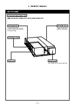
Page 14: ...FE MMD AP0961HFE Earth screw It is included in the electric parts box Air intake port Intakes the fresh air with the inlet flange Air supply port Cools heats the fresh air and sends it into the room with the air supply flange Drain pan Air supply sensor 4 OWNER S MANUAL ...

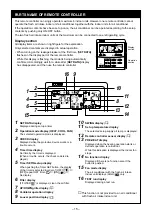
Page 15: ...n display 10 SWING display 11 Set up temperature display The selected setup supply air temp is displayed 12 Remote controller sensor display 13 PRE HEAT display Displayed when the heating operation starts or defrosts operation is carried out While this indication is displayed the indoor fan stops 14 No function display Displayed if there is no function even if the button is pushed 15 Fan mode disp...

Page 16: ...roller even if pushing the FAN button it means that a fan is not connected 5 Filter reset button Resets Erases FILTER display 6 Unit button 7 SWING FIX button No function 8 Operation lamp Lamp is lit during the operation Lamp is off when stopped It flashes when operating a protection device or abnormal occurred 9 ON OFF button When the button is pushed operation starts and it stops by pushing the ...

Page 17: ...tate by pushing the ON OFF button Preparation Turn on the main power switch and or the leakage breaker When the power supply is turned on display section is displayed on the remote controller After the power supply is turned on the remote controller does not accept an operation for approx 1 minute but it is not a failure REQUIREMENT While using the air conditioner operate it only with ON OFF butto...

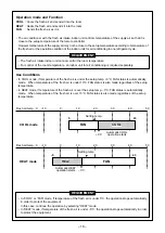
Page 18: ...re of the fresh air is under the setup temp 3 C FAN status is automatically made When temperature of the fresh air is under 19 C FAN status is also made regardless of the setup temperature In HEAT mode if temperature of the fresh air is over the setup temp 3 C FAN status is automatically made When temperature of the fresh air is over 15 C FAN status is also made regardless of the setup temperature...

Page 19: ...A and timer time displays flash 2 Push TIME to select SET TIME For every push of button the set time increases in the unit of 0 5 hr 30 minutes The maximum set time is 168 hr For every push of button the set time decreases in the unit of 0 5 hr 30 minutes The minimum set time is 0 5 hr 3 Push SET button SETTING display disappears and timer time display goes on When ON timer is activated timer time...

Page 20: ...k the customer to keep the Installation Manual together with the Owner s Manual CAUTION New Refrigerant Air Conditioner Installation THIS AIR CONDITIONER ADOPTS THE NEW HFC REFRIGERANT R410A WHICH DOES NOT DESTROY OZONE LAYER The characteristics of R410A refrigerant are easy to absorb water oxidizing membrane or oil and its pressure is approx 1 6 times higher than that of refrigerant R22 Accompani...

Page 21: ...ion of the unit To avoid personal injury with sharp edges be careful when handling parts Perform installation work properly according to the Installation Manual Inappropriate installation may result in water leakage electric shock or fire When the air conditioner is installed in a small room provide appropriate measures to ensure that the concentration of refrigerant leakage occur in the room does...

Page 22: ...line of the multi system The allowable total capacity of the two fresh air intake indoor units shall be 30 or less against the total capacity of the indoor units including the fresh air intake indoor units Keep the height difference between the fresh air intake indoor units to 0 5m or less The fresh air intake indoor unit is usually used together with the indoor units on one refrigerant cycle of t...

Page 23: ...re drained water will not cause any problem Avoid installing in the following places Place exposed to air with high salt content seaside area or place exposed to large quantities of sulfide gas hot spring Should the unit be used in these places special protective measures are needed Place exposed to oil vapor oil smoke or corrosive gas Place where organic solvent is used nearby Place close to a ma...

Page 24: ...ially inside of the ceiling may become high humidity atmosphere dew point temperature 30 C humidity 80 or higher 1 Installation to inside of the ceiling with tiles on the roof 2 Installation to inside of the ceiling with slated roof 3 Installation to a place where inside of the ceiling is used for pathway In the above cases additionally attach the thermal insulator Glass wool etc to all positions ...

Page 25: ...FIX TIME MODE VENT UNIT SET CL FILTER RESET TEST TIMER SET 16 120 4 2 7 120 Wired remote controller RBC AMT31E Mounting of the remote controller Sold separately For mounting of the remote controller refer to the Installation manual attached to the remote controller Do not place the remote controller in the direct sunlight or at place near a heater Model MMD AP0481HFE AP0721HFE AP0961HFE A B C D 89...

Page 26: ...ole on the ceiling of installation and perform unit piping piping until the wiring connecting port refrigerant water supply drain and wiring work power supply connecting wiring remote controller wiring 3 Mount the hanging bolt Hanging bolt size Use M10 Hanging up of unit CAUTION This unit is incorporated with drain pump and float switch Never incline the main unit Otherwise malfunction of the floa...

Page 27: ...e inner liner of the duct and the vibration proof rubber to the hanging bolt Main unit Hanging bolt Nut Upper side Washer Upper side Thermal insulator Hanging bracket main unit Washer Lower side Nuts Lower side Using a level vial or vinyl hose check whether the indoor unit is hung horizontally or not Thermal insulation Front view Side view Install the main unit within 5mm while lowering the drain ...

Page 28: ...ly heat insulation for the duct to prevent dewing Recommended material Glass wool or foam polyethylene Thickness 25mm When welding the duct at the site sparks may enter in the air filter or thermal insulator To avoid spread of the fire cover the duct with iron plate etc When penetrating metal lath wire lath or metal plank with the metal duct isolate the duct from the wall electrically Set the canv...

Page 29: ...0 250 1080 10 Ø8 hole 250 12 12 25 370 344 394 25 25 25 215 65 65 775 725 8 Ø8 hole 12 12 25 406 380 430 25 25 25 215 215 250 250 65 65 630 580 6 Ø8 hole 12 12 REQUIREMENT If the air conditioner unit and the canvas joint are connected with the rivets the fan and the refrigerating cycle cannot be checked Be sure to use the flange as shown in the above and tighten it by the bolts Fixing bolts M6 x 1...

Page 30: ...duct at descending inclination so that water can be drained even if rainwater enters in 2 Air supply duct Connect the air supply duct Procured locally to the Air supply flange Wrap aluminum tape around connecting part of the air supply port flange and duct or apply packing so that air does not leak Product main unit Check port 600 600 1 Heat insulator 1 Canvas duct 1 Wall Canvas duct 1 Sold separa...

Page 31: ...er leak Do not apply strength to the connecting part with the drain pipe Do heat insulating securely to the indoor drain pipe Be sure to do heat insulating to the connecting part with the indoor unit Incomplete heat insulating may cause dewing Do not directly connect the drain pipe to the drainage etc with ammonia smell otherwise there is a possibility that ammonia ingredient of the drainage passe...

Page 32: ...ng material and dimensions Piping material Model Pipe size mm Gas side Liquid side Phosphor deoxidization seamless pipe for air conditioner MMD AP0481HFE MMD AP0721HFE AP0961HFE Ø15 9 Ø22 2 Ø9 52 Ø12 7 Use a clean and new pipe and check that impurity such as dust oil moisture etc does not adhere in the pipe Pipe Forming End Positioning Flaring 1 Cut the pipe with a pipe cutter 2 Insert a flare nut...

Page 33: ...g process Perform heat insulating for pipes at liquid side and gas side separately In cooling time temperature at both liquid and gas sides becomes lower Therefore perform heat insulating process sufficiently to avoid dewing For heat insulator of pipe at gas side be sure to use one with heat resisting temp 120 C or more REQUIREMENT Apply the heat insulation to the pipe connecting section of the in...

Page 34: ...n earth leakage breaker If an earth leakage breaker is not installed an electric shock may be caused REQUIREMENT For power supply wiring strictly conform to the Local Regulation in each country For wiring of power supply of the outdoor units follow to the Installation Manual of each outdoor unit Never connect 220 240V power to the terminal blocks A B U1 U2 for control wiring Otherwise the system w...

Page 35: ...s cannot be parallel to contact each other and cannot be stored in the same conduits If doing so a trouble may be caused on the control system due to noise etc Group control between the fresh air intake indoor unit and the normal air conditioner unit is impossible Remote controller inter unit wiring Remote controller Indoor unit L1 L2 Ln Max 8 units Indoor unit Indoor unit Indoor unit Remote contr...

Page 36: ...roller wire Field supply Remote controller unit A B Terminal block Wiring diagram Address setup Set up the addresses according to the Installation Manual attached to the outdoor unit Indoor power supply 220 240V 50Hz 220V 60Hz Outdoor power supply 380V 415V 50Hz 380V 60Hz Earth leakage breaker Header outdoor unit Remote controller Pull box Earth leakage breaker power switch Pull box Pull box Heade...

Page 37: ...ode indicates other than 10 push TEST button to erase the display and then retry the operation from the first step For some time after TEST button has been pushed the operation of the remote controller cannot be accepted In a group control the firstly displayed indoor unit No becomes the center unit The display changes according to the indoor unit model Every pushing UNIT button the indoor unit No...

Page 38: ...cleaning can be changed Follow to the basic operation procedure 1 2 3 4 5 6 For the item code in Procedure 3 specify 01 For the Set data in Procedure 4 select the setup data of filter sign lighting terme from the following table Setup data 0000 0001 0002 0003 0004 Filter sign lighting term None 150H 2500H At shipment from factory 5000H 10000H ...

Page 39: ...00 1000 900 800 2 0 1 5 1 0 0 5 350 300 250 200 150 100 50 0 External static pressure Pa Motor current for fan A High static pressure tap High static pressure tap High static pressure tap High static pressure tap Mid static pressure tap Mid static pressure tap Mid static pressure tap Mid static pressure tap Air volume m h 1200 1100 1000 900 800 2 0 1 5 1 0 0 5 350 300 250 200 150 100 50 0 External...

Page 40: ...re tap 50Hz 240V Air volume m h 1200 1100 1000 900 800 2 0 1 5 1 0 0 5 350 300 250 200 150 100 50 0 External static pressure Pa Motor current for fan A Air volume m h 1200 1100 1000 900 800 2 0 1 5 1 0 0 5 350 300 250 200 150 100 50 0 External static pressure Pa Motor current for fan A 60Hz 220V Low static pressure tap Low static pressure tap Mid static pressure tap High static pressure tap ...

Page 41: ... tap Low static pressure tap Low static pressure tap 50Hz 220V Air volume m h 1800 1600 1400 1200 3 0 2 5 2 0 1 5 350 300 250 200 150 100 50 0 External static pressure Pa Motor current for fan A 1800 1600 1400 1200 Air volume m h 3 0 2 5 2 0 1 5 350 300 250 200 150 100 50 0 External static pressure Pa Motor current for fan A 50Hz 230V Mid static pressure tap Mid static pressure tap Mid static pres...

Page 42: ...sure tap 1800 1600 1400 1200 1800 1600 1400 1200 50Hz 240V Air volume m h 3 0 2 5 2 0 1 5 350 300 250 200 150 100 50 0 External static pressure Pa Motor current for fan A Air volume m h 3 0 2 5 2 0 1 5 350 300 250 200 150 100 50 0 External static pressure Pa Motor current for fan A 60Hz 220V High static pressure tap Low static pressure tap Mid static pressure tap High static pressure tap ...

Page 43: ...Hz 220V Air volume m h 2300 2100 1900 1700 1500 2300 2100 1900 1700 1500 3 5 3 0 2 5 2 0 350 300 250 200 150 100 50 0 External static pressure Pa Motor current for fan A Air volume m h 3 5 3 0 2 5 2 0 350 300 250 200 150 100 50 0 External static pressure Pa Motor current for fan A 50Hz 230V Low static pressure tap Low static pressure tap High static pressure tap Low static pressure tap High static...

Page 44: ... tap 2300 2100 1900 1700 1500 2300 2100 1900 1700 1500 50Hz 240V 60Hz 220V Air volume m h 3 5 3 0 2 5 2 0 350 300 250 200 150 100 50 0 External static pressure Pa Motor current for fan A Air volume m h 3 5 3 0 2 5 2 0 350 300 250 200 150 100 50 0 External static pressure Pa Motor current for fan A Mid static pressure tap Low static pressure tap Mid static pressure tap High static pressure tap ...

Page 45: ... 50 60Hz Remarks At shipment from factory Lead wire for changing the external static pressure When changing the external static pressure is necessary change connection of this lead wire Electric parts box 4P terminal block 2P terminal block Control P C board Fan motor Blue Black Orange at shipment of factory F1 F2 F3 F4 Orange FM Fan motor Blue Black Orange at shipment of factory F1 F2 F3 F4 Orang...

Page 46: ...e turning on the power supply carry out the following items 1 Using 500V megger check there is 1MΩ or more between the terminal block of the power supply and the earth If 1MΩ or less is detected do not run the unit 2 Check that all the valves of the outdoor unit are fully opened Never push the electromagnetic contactor to carry out a forced test operation It is very dangerous because a protective ...

Page 47: ... the operation status can be known Using this self diagnosis function a trouble or position with error of the air conditioner can be found as shown in the table below Check code list The following list shows each check code Find the check contents from the list according to part to be checked In case of check from indoor remote controller See Main remote controller display in the list In case of c...

Page 48: ...ys Indoor protection Outdoor protection Sensor Compressor protection etc Display A C E F H J L P Classification Unused Central control system error Communication system error Each sensor error Failure Compressor protective system error Unused Setup error Other errors Protective device operation 1 2 3 ON OFF FAN TEMP SWING FIX TIME MODE VENT UNIT SET CL FILTER RESET TEST TIMER SET CODENo 13 MAINTEN...

Page 49: ... filter Refrigerant pipe connecting port Gas side M Refrigerant pipe connecting port Liquid pipe N C D E F Blow off port Discharge port connecting flange K Accessory for main unit of product Discharge temp sensor 406 38 38 A G H I J 406 51 35 G H I J Suction port Suction port connecting flange L Accessory for main unit of product Note 1 The above figure indicates Model MMD AP0721HFE and AP0961HFE ...

Page 50: ...D GRY WHI RED GRY WHI RED GRY WHI RED GRY RED T10A 250V CN044 BRW Power supply circuit Sub P C board MCC 1520 CN02 YEL CN01 WHI TR1 Control P C Board for Indoor Unit MCC 1403 B A BLK Parts name Fan Motor Running Capacitor Transformer Intake air temp sensor Blow temp sensor Temp sensor Fan motor control relay Drain control relay Pulse Motor Valve Fuse for fan motor Fan motor control relay Drin Pump...

Page 51: ...02 YEL CN01 WHI TR1 Control P C Board for Indoor Unit MCC 1403 B A BLK Parts name Fan Motor Running Capacitor Transformer Intake air temp sensor Blow temp sensor Temp sensor Fan motor control relay Drain control relay Pulse Motor Valve Fuse for fan motor Fan motor control relay Drin Pump motor Float Swotch Symbol FM1 FM2 RC1 RC2 TR1 TA TF TC1 TC2 TCJ RY005 007 RY002 PMV F1 F2 43F1 43F2 DP FS Termi...

Page 52: ...2 6P Blue 1 Super heat control function in cooling operation 2 Under cool control function in heating operation 3 Cooling refrigerant oil recovery function 4 Heating refrigerant oil recovery function Connector CN104 2P Yellow 1 For detection of outdoor suction temperature Connector CN100 3P Brown 1 For super heat control of PMV in cooling operation Connector CN101 2P Black 1 For under cool control...

Page 53: ...eration 25 C 1 Differed from other indoor air conditioners the fresh air intake inddor unit usually operates with the maximum capacity 1 Fresh air intake indoor unit controls PMV using the corrected value of each sensor according to the operation mode COOL SH control is performed by correcting indoor coil temp TC1 and inlet air temp from outside TA HEAT UC control is performed by correcting indoor...

Page 54: ... temperature TA COOL At TA 19 C HEAT At TA 15 C or TA 5 C 2 The thermostat is forcedly off by outdoor suction temperature TA and remote controller setting temperature TS COOL At TA TS 3 C HEAT At TA TS 3 C 1 The thermostat is forcedly off by outdoor suction temperature TA COOL FAN At TA 5 C HEAT At TA 5 C 2 After fan OFF status continued for 60 minutes turn on the fan for 1 minute The forced fan O...

Page 55: ...ol function resets Reset conditions TC1 12 C and TC2 12 C and TCJ 12 C 20 minutes passed after stop P1 Q1 TC1 10 C 5 C 0 C TC2 TCJ 10 C 14 C value When power supply is turned on if the value is under this temperature thermostat is forcedly off 2 The cooling operation is performed as follows based on the detected temperature of TC2 sensor and TCJ sensor When M zone is detected for 45 minutes thermo...

Page 56: ...in opening angle When the indoor air conditioner which stops in which thermostat is off or which operates FAN performs the following control by receiving the heating refrigerant oil recovery signal from the outdoor unit Opens PMV of the indoor air conditioner with certain opening angle Detects temperature of TC2 and closes PMV 1 For 5 minutes after start of operation the operation continues forced...

Page 57: ...nd by displayed on the remote controller 1 Defrosting Indoor fan stops because unit is under defrost operation Remarks Operation stand by display Heating stand by display In case of TCC LINK central control Operation from TCC LINK central controller Single Central 1 Central 2 Central 3 Central 4 Operation on RBC ATM31E START STOP Operation Timer Temp Air speed Air direction setting selection setti...

Page 58: ...rge cassette Floor standing only Outside error input TCJ sensor TC2 sensor TCI sensor CHK DISP Used for servicing Remote controller inter unit wire Optional output HA T10 Remote controller power supply LED Indoor Outdoor communication Also used for communication of the central control system Indoor Outdoor communication Spare EEPROM PMV output Microcomputer operation LED Power transformer Secondar...

Page 59: ...remote controller DN 31 HA Start Stop input J01 Provided None Pulse At shipment from factory Static input selection Operation stop of RBC AMT31E is allowed prohibited by input ON during operation Answer back of HA ON during output of alarm ON during defrosting of outdoor unit ON during real thermo ON Compressor ON ON when operation mode is COOL ON when operation mode is HEAT ON when indoor fan is ...

Page 60: ...r than COOL HEAT mode Temperature cannot be adjusted during test operation Detection of error is performed as usual When test operation finished push ON OFF ON OFF button to stop operation The same display as Procedure 1 is displayed Push CHECK button to release the Test operation mode TEST TEST display on the display part disappears and the status becomes normal stop status TEST 10 3 Function dur...

Page 61: ...r unit The short plugs for the float switch are already inserted at shipment from the factory 3 Restricted to the normal time if DISP pin CN72 on indoor P C board is short cut in addition to short circuited CHK pin CN71 on indoor P C board you can set opening of indoor PMV only to the minimum opening 30pls Opening DISP pin sets opening to the maximum opening 1500pls again Releasing Open the CHK pi...

Page 62: ... button displays the indoor air conditioner No in the group control one by one In this time the fan of the selected indoor air conditioner only operates ò 3 Using temperature setting buttons specify the item code DN ò 4 Using timer time buttons select a setting data ò 5 Push SET button OK if display goes on To change the selected indoor air conditioner return to procedure 2 To change an item to be...

Page 63: ...4 No 64 unit 0099 Undefined 0000 No priority 0001 Priority 0000 AUTO Cooling Heating provided 0001 No AUTO Cooling Heating Automatic selection by connected outdoor unit 0000 Heat pump 0001 Cooling only No AUTO HEAT display 0000 1 way Air Discharge Cassette Type 0001 4 way Air Discharge Cassette Type 0037 0000 Undefined 0001 0034 0001 No 1 unit 0028 No 28 unit 0001 No 1 unit 0064 No 64 unit 0000 Si...

Page 64: ...operation is performed 3 Error signal Outputs during alarm Serial communication error or indoor Outdoor protective device is operating 2 Wiring diagram using the remote control interface TCB IFCB4E Input IFCB4E No voltage ON OFF continuous signal Output No voltage contact For operation error display Contact capacity Up to Maximum AC240V 1A 1 2 3 4 5 6 CN061 T10 YEL 1 2 3 4 1 2 3 4 5 6 CN13 CN06 St...

Page 65: ...e indoor air conditioner address of the master unit of the group control In this time the fans of the selected indoor air conditioners operate ò 2 Every pushing UNIT button displays the indoor air conditioner No in the group control one by one In this time the fan of the selected indoor air conditioner only operates ò 3 Using temperature setting buttons specify the item code ò 4 Using timer time b...

Page 66: ...ohibited Status that card is taken off from the card switch box In a case of the card switch box which does not become the above contact operation convert it to relay with b contact 2 Operation Operate the wired remote controller switch in the following procedure Operation should be performed during stop of the unit 1 Push SET CL TEST buttons concurrently for 4 seconds or more ò 2 Using setup temp...

Page 67: ...ode 04 Using the timer time buttons select the setting data 0001 Priority 0001 Without priority 0000 Push SET button When the display changed from flashing to lighting the setting finished After finish of setting push TEST button Setting has determined When pushing TEST button the display disappears and the status enters in the normal stop status After pushing TEST button operation from the remote...

Page 68: ...off temp TF Indoor PMV opening Connected No of indoor air conditioners Total HP of connected indoor air conditioners Connected No of outdoor units Total HP of outdoor units Unit C C C C C C C pls unit HP unit HP Display type 1 1 1 1 1 1 1 10 10 10 Single data of outdoor unit Note 4 5 Item code 10 11 12 13 14 15 16 17 18 19 1A 1B 1D 1E 1F Data name Compressor 1 discharge temp Td1 Compressor 1 disch...

Page 69: ...ompressor does not operate Indoor fan does not rotate Outdoor fan does not rotate or air speed exchanges Indoor fan does not stop Remote controller cannot use for Start Stop operation Items to be checked Isn t it delaying for 3 minutes 3 minutes after compressor OFF Isn t it during thermostat OFF Isn t it during operation of fan or timer Isn t it initial communication of the system Isn t the outsi...

Page 70: ... motor microcomputer Regular communication is impossible between indoor master and follower units Open short of heat exchanger temp sensor TCJ was detected Open short of heat exchanger temp sensor TC2 was detected Open short of heat exchanger temp sensor TC1 was detected Open short of outdoor suction temp sensor TA was detected Open short of blow off temp sensor TF was detected Indoor EEPROM error...

Page 71: ...nsor TK1 to TK4 error Compressor 2 case thermostat operation Oil level detection circuit system error Error contents There is no communication from indoor unit Decrease of connected indoor units Signal cannot be sent to indoor unit There is no communication from outdoor unit at indoor side Multiple indoor units having same address exists Detected also at indoor unit side Automatic indoor address i...

Page 72: ... phase Phase order to motor is incorrect Motor may not rotate clockwise or may not rotate High temp error is detected on temp sensor TH built in outdoor IGBT There is indoor unit which stops abnormally by detection of overflow in one line Detected by indoor unit It is judged as liquid back occurred from refrigerating cycle status Continuation of high temperature of outdoor suction temp sensor TS1 ...

Page 73: ...ns concurrently for 4 minutes or more to call the service check mode The service check goes on the item code is firstly displayed and then the contents of the latest alarm are displayed The indoor air conditioner No in which alarm generated and the alarm contents are displayed ò 2 To monitor other error history push TEMP TEMP buttons to change the error history No Item code Item code Latest à Item...

Page 74: ...st one push TEMP and select the item code 01 to 04 5 To confirm alarm of the other group push ZONE and GROUP select the group No Do not push CL button otherwise all the alarm histories of the currently selected group are deleted 6 To finish the service check push button 1 Confirmation and check When a trouble occurred on the air conditioner the check code and the indoor air conditioner No are disp...

Page 75: ...i cation from outdoor unit When signal is not sent for a certain period from the indoor unit which has been used to send signals E06 is normally displayed Transmission from outdoor to indoor cannot continue for 30 seconds Multiple indoor unit address setup are duplicated In 2 remote controller control including wireless both are setup as master Header indoor unit stops and other indoor unit is ope...

Page 76: ...ion Turn on SW09 Bit 2 on I F P C board of outdoor header unit Regular communication between indoor header and follower units There are multiple outdoor header units in 1 line There is none of outdoor header unit in 1 line Unit of other line was connected when indoor automatic address started Transmission of other outdoor unit was unavailable for 30 seconds or more Check item position Setup the ad...

Page 77: ...Resistance value of sensor is infinite or zero Open Short Check item position Note Do not set up the outdoor address manually Outdoor is performing backup Check the power of outdoor unit Is the power turned on Check connection of inter unit wire or disconnection between outdoor units Check the connector connection for communication on outdoor P C board Check outdoor P C board I F error Check the c...

Page 78: ...pressor Indoor P C board did not operate normally Outdoor P C board I F did not operate normally Check item position Check connection of TL sensor connector Check characteristics of TL sensor resistance value Check outdoor P C board I F error Check connection of TO sensor connector Check characteristics of TO sensor resistance value Check outdoor P C board I F error Check connection cabling of TA ...

Page 79: ...nd phase missing Check connector terminal connection on IPDU P C board Check conduction of case heater Check activation error due to liquid stagnation in compressor Check outdoor P C board IPDU error Check outdoor MG SW or OCR Check cabling of current detection circuit system Check outdoor P C board IPDU error Check compressor 1 case thermo circuit Connector cable P C board Check full opening of s...

Page 80: ... connection of TK3 sensor connector Check characteristics of TK3 sensor resistance value Check outdoor P C board I F error Check connection of TK4 sensor connector Check characteristics of TK4 sensor resistance value Check outdoor P C board I F error Check compressor 2 case thermo circuit Connector cable P C board Check full opening of service valve Gas and liquid side Check outdoor PMV clogging P...

Page 81: ...fferent refrigerant pipe system Indoor units with priority were duplicated Indoor units with priority were duplicated At least one indoor unit connected to a group existed in the individual indoor units Address was not yet set up Indoor unit capacity was unset On the I F P C board for service jumper line was not cut according to the model Duplicated central control addresses There were more than f...

Page 82: ...ck clogging of outdoor PMV PMV1 2 Check characteristics of TD1 sensor resistance value Check refrigerant shortage Check leakage of SV41 circuit Check SV4 circuit Miscabling and misinstallation of SV41 and SV42 Check Pd pressure sensor error Check full opening of outdoor service valves Gas side Liquid side Check outdoor fan error Check outdoor fan motor error Check clogging of outdoor PMV PMV1 2 Ch...

Page 83: ...ry clogging of oil return circuit from oil separator Check leakage of check valve of the main discharge pipe Check refrigerant shortage Check full open of outdoor service valves gas side liquid side Check outdoor PMV clogging PMV1 2 Check characteristics of TS1 sensor resistance value Check leakage of SV4 circuit Check refrigerant shortage Check outdoor PMV clogging PMV1 2 Check characteristics of...

Page 84: ... more passed after start time Sub code C Heat sink sensor TH of fan IPDU detected 95 C error Sub code D Heat sink sensor TH of fan IPDU detected short circuiting or open Sub code E nput power supply voltage of the fan IPDU over the setup value was detected Input power supply terminal of the fan IPDU was unconnected Power supply P C board error of the fan IPDU Instantaneous over current was detecte...

Page 85: ... Error detection condition Signal is not transmit from central control device Signal is not received from central control device Error was input in general purpose control device control interface An error occurred in follower unit of the group control P30 is displayed only on the central control remote controller Central control addresses were duplicated Check item position Check central control ...

Page 86: ... kW Caracteristics 3 Temperature C Resistance kW 10 C or lower Resistance kW 10 C or higher Temperature C TC1 TC2 TCJ sensor TA TF sensor 20 10 0 10 20 40 30 50 200 100 20 10 0 0 10 0 10 20 40 30 50 60 70 11 5 Sensor Characteristics ...

Page 87: ...to AP0481 type two are provided to AP0721 AP0961 types respectively AP0481 type has the same configuration as AP0721 AP0961 types Remove Faston terminals of which wire color are blue 1 orange 2 black 3 in the fan motor lead wires Remove the white and blue connectors Cut binding tie One fan motor to AP0481 type two fan motors to AP0721 AP0961 type are provided Photo AP0961 type Status which tie wra...

Page 88: ... box Removed status Take off the self tapping M4 screws 3 positions Cover plate Remove the cover plate Take off M5 screws 8 positions Status which all the fan assembly are pulled out Pull out the fan toward you Take off the self tapping M4 screws 3 positions 4 Pull out the fan toward you ...

Page 89: ...he fan assembly from the air intake unit Relay terminal block cover there is the relay terminal block inside of it Fan motor Fan case Fan Motor base Remove the connector and Faston terminal Remove the earth screw Remove the relay terminal block cover ...

Page 90: ...ove the fan motor assembly from the fan assembly Take off M4 screws 2 positions Z view Z view Take off M4 screws 2 positions Take off M4 screws 2 positions Take off M8 screws 4 positions mounting the motor base ...

Page 91: ...f screws in assembling time Check that the air blows off and the fan does not hit with the fan case and also check there is no abnormal noise Take off M4 screws 4 positions from the bell mouth Loosen the setscrews When replacing the fan motor set it so that the model name label directs upward Remove the fan Loosen M4 screws 2 positions of the tightening band remove the tightening band and the fixi...

Page 92: ...indoor air conditioners connected to the remote controller CASE 2 Under condition before replacement power supply of the indoor air conditioner is unable to turn on and the wired remote controller cannot be operated due to trouble of the power supply circuit to the remote controller P C board error Replacement of EEPROM IC10 For parts layout and replacing method see EEPROM Layout diagram in p 94 R...

Page 93: ...the indoor air conditioner to be replaced and the remote controller to 1 1 Turn on power supply of the indoor air conditioner by any one of the following methods according to the system configuration A Case of single individual operation Turn on power supply of the indoor air conditioner and proceed to 3 B Case of group operation a Power supply of the replaced indoor air conditioner only can be tu...

Page 94: ...ign lighting time 6 In this time compare the contents of the displayed setting data p 95 with contents noted in 1 p 93 and the customers information a If data differs from them change data to the noted contents by TIME buttons and then push SET button OK if the display goes on b Do nothing if data matches with them 7 Change the item code DN by TEMP buttons Check the contents of setting data as sam...

Page 95: ...10 Initial setup value of EEPROM installed on the service P C board Set type code and capacity code besides set DN C8 0001 Setup data 0000 0001 0002 0003 0004 0005 0006 0007 0008 0009 0010 0011 0012 0013 0014 0016 Type 1 way Air Discharge Cassette 4 way Air Discharge Cassette 2 way Air Discharge Cassette 1 way Air Discharge Cassette Compact type Concealed Duct Standard Slim Duct Concealed Duct Hig...

Page 96: ...ND PARTS LIST 14 1 Fresh Air Intake Indoor Unit for S MMS MMD AP0481HFE Location No Part No Description MMD AP0481HFE 201 4312C014 Motor Fan STF200 160 4AR 1 207 43122109 Case Fan 1 209 43020352 Fan 1 218 4316V194 Remote Controller SX A1EE 1 219 4316V195 Remote Controller SX A11JE2 1 220 4316V196 Remote Controller EX W2JE2 1 221 43139154 Band Motor Left 2 222 43139155 Band Motor Right 2 226 431605...

Page 97: ...7 219 220 218 235 221 222 Location No Part No Description MMD AP0721HFE MMD AP0961HFE 201 4312C014 Motor Fan STF200 160 4AR 2 2 207 43122109 Case Fan 2 2 209 43020352 Fan 2 2 218 4316V194 Remote Controller SX A1EE 1 1 219 4316V195 Remote Controller SX A11JE2 1 1 220 4316V196 Remote Controller EX W2JE2 1 1 221 43139154 Band Motor Left 4 4 222 43139155 Band Motor Right 4 4 226 43160549 Terminal Bloc...

Page 98: ...Ass y 1 1 210 43149355 Nut Flare 3 8 IN 1 211 43049776 Socket 3 8 IN 1 212 43047609 Bonnet 1 213 43047688 Nut Flare 1 2 IN 1 1 214 43149332 Socket 1 1 215 43147195 Bonnet 1 2 IN 1 1 216 4314Q053 Strainer DIA 21 1 217 4314Q052 Strainer DIA 45 1 1 223 43149352 Nut Flare 5 8 IN 1 224 43149354 Socket 5 8 IN 1 225 43194029 Bonnet 1 228 43147649 Strainer 1 1 1 229 43107215 Holder Sensor 1 1 1 230 430199...

Page 99: ... O S b m O W R b m O S O b O X b m O T O b m O W P b O R b m O S S h b O S O b m P O P s b Q s b d Q b m P O Q s b i d P b m P O O s b P d R b m O U P b m O U O q b b m O S P l o R Q P P Q Q Q i k j 1 F F3 F2 F4 e m Q 1 F F3 F2 MMD AP 072F 096F F4 e m P T10A 250V q FAN1 FAN2 43F2 U T V 43F1 D F2 F1 T10A 250V D r i m j Ô Â Â 402 401 406 411 408 409 413 410 405 404 414 403 412 MMD AP0481HFE MMD AP07...

Page 100: ... the number of high concentration buildings however the installation of multi air conditioner systems is on the increase because of the need for effective use of floor space individual control energy conservation by curtailing heat and carrying power etc Most importantly the multi air conditioner system is able to replenish a large amount of refrigerant compared with conventional individual air co...

Page 101: ...TOSHIBA CARRIER CORPORATION 2 CHOME 12 32 KONAN MINATOKU TOKYO 108 0075 JAPAN Copyright 2007 TOSHIBA CARRIER CORPORATION ALL Rights Reserved ...

Reviews: