– 92 –
13. P.C. BOARD REPLACING PROCEDURES
Part code
431-6V-343
Applicable Model
MMD-AP
∗∗∗
HFE series
P.C. board Model
MCC-1403
Label on P.C. board
03RD M02
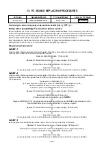
<Set the type code and capacity code and then set DN [C8] = [
0001
].>
Notice when assembling P.C. board for indoor service
Before replacement, in the non-volatile memory (Hereinafter said EEPROM, IC10) installed on the indoor P.C.
board, the important setting data such as type and capacity codes exclusive to the model at shipment from
factory and moreover the line/indoor/group address which were set up (automatically/manually) at installation
time are stored. Assemble and replace P.C. board for indoor service as described below.
After replacement, check the indoor air conditioner No. or group master/follower units to confirm whether
setting contents are correct or not, and also confirm the cycle by a test run.
<Replacement procedure>
CASE 1
Under condition before replacement, power supply of the indoor air conditioner is able to turn on, and the setting
contents can be read-out from the wired remote controller.
Read-out of EEPROM data
∗
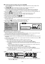
1 (See p.93)
ò
Replace P.C. board for service & turn on power supply.
∗
2 (See p.93)
ò
Write-in the read out EEPROM data
∗
3 (See p.94)
ò
Reset the power supply.
(In group operation control, all the indoor air conditioners connected to the remote controller.)
CASE 2
Under condition before replacement, power supply of the indoor air conditioner is unable to turn on, and the wired
remote controller cannot be operated due to trouble of the power supply circuit to the remote controller.
(P.C. board error)
Replacement of EEPROM (IC10)
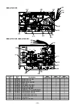
(For parts layout and replacing method, see EEPROM Layout diagram in p.94)
Remove EEPROM installed on P.C. board before replacement
and then replace it with EEPROM of P.C. board for service.
ò
Replace P.C. board for service & turn on power supply.
∗
2 (See p.93)
ò
Read-out of EEPROM data
∗
1 (See p.93)
If read-out operation is impossible, go to
CASE 3
.
ò
Replace EEPROM (IC10) (For parts layout and replacing method, see EEPROM Layout diagram in p.94)
Replace EEPROM again. (Set EEPROM to P.C. board as original.)
ò
Replace P.C. board for service & turn on power supply.
∗
2 (See p.93)
ò
Write-in the read out EEPROM data.
∗
3 (See p.94)
ò
Reset the power supply.
(In group operation control, all the indoor air conditioners connected to the remote controller.)
CASE 3
Before replacement, EEPROM is defective and read-out of setup contents is unavailable.
Replace P.C. board for service & turn on power supply.
∗
2 (See p.93)
ò
Based upon customers’ information, write the setting data such as high-ceiling setting,
option connection setting in EEPROM.
∗
3 (See p.94)
ò
Reset the power supply.
(In group operation control, all the indoor air conditioners connected to the remote controller.)

